How to model the Application Domain Model of STEPLIB
Contents:
Overview
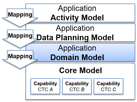
Figure 64 The STEP Architecture
The Application Domain model is the AP view of the Core model.
The Application Domain model is the layer of the information model that describes the information requirements and constraints of a specific application context.
The Application Domain model is a specific view of constrained selection and of the Core model controlled by the requirement of the Conceptual model in order to fulfil the Application Protocol requirements.
This page uses a simple example to describe how to model the the Domain Model using SysML in MagicDraw 18.4.
Step by Step guide
The modelling steps are:
- Preparation
- Original instructions from PLCSlib
- Descriptions
- Problem and Rationale Comments
- Block Definition Diagrams - general rules
- Entity Types
- Properties and Associations
- Directed Association - Reference Property
- Directed Composite Association - Part Property
- Directed Composite Association - Value Property
- Directed Inverse-Composite Association - Reference Property
- Bi-Directed Association - Reference Property
- Bi-Directed Composite Association Part and Reference Property
- Redefined Properties
- Validation Constraints
- Query-like services
Preparation
Important
Prerequistes
This assumes that the environment is already set up. See Getting Started - MagicDraw for more details
Original instructions from PLCSlib
Caution
This video is out of date. It shows the steps from PLCSlib using Magicdraw 17.4
This video explains what a template is, how it is represented and basic creation and completion tasks
Caution
This video is out of date. It shows the steps from PLCSlib using Magicdraw 17.4
This video show how to creating the template block and identifying public properties
Todo
the step-by-step for this section
- create a new package (no longer needed)
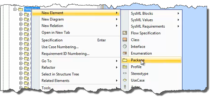
Figure 65 Adding a new Package for the Template
- Add a block
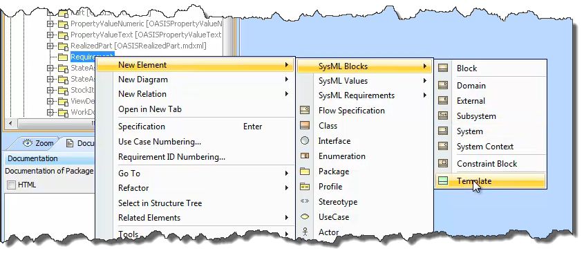
Figure 66 Adding a new Block
This adds a new block in the tree. This should be renamed.
- Add diagram to the package and add the template
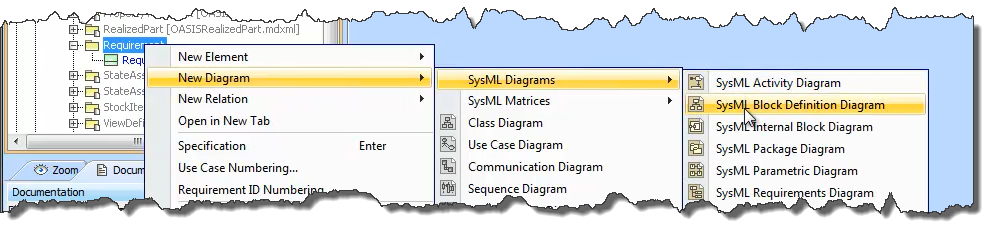
Figure 67 Adding a new diagram
Add a new diagram and rename this to “Template”
Add a stylesheet (to be defined)
Drag the template onto the diagram
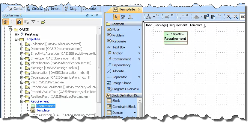
Figure 68 Adding a Template to a diagram
Add owner above
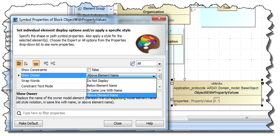
Figure 69 Add Owner Above Element Name
Change colours
Descriptions
Descriptions should be added to all packages, blocks (including auxiliaries), Enumerations, public properties and constraints.
Description format
The WG12 Review Checklist (QCN265) states “204. The definition of each EXPRESS/SysML construct is unambiguous and understandable, grammatically correct, and defines the concept (not simply restates the EXRESS/SysML)”.
See Supplementary Directives for the official directives.
See also Naming.
The following are a summary of the directives.
- Text in General
The following table summarises the do’s and dont’s for the text of descriptions and definitions.
do use... don’t use... see also “instances of <entity name>” plural e.g. <entity name>s 6.4.9.4 Plurals of “shall” “shall not” “is required to” “only...is permitted” “must” “most not” 4.8 Acceptable wording “should” “should not” “is recommended that...” “ought to...” 4.8 Acceptable wording “may” “need not” (i.e. permissable in limits of standard) “is permitted” “is allowed” 4.8 Acceptable wording 4.8 Acceptable wording “can” “cannot” (i.e. something that is possible) “to be able to” “it is possible to” 4.8 Acceptable wording <note></note> ot “that is” “i.e.” 4.8 Acceptable wording <example></example> “e.g.” “etc” (“for example” ) 4.8 Acceptable wording and/or 4.10 Words to avoid datum <xyz>s (e.g. datum points) datums 4.10 Words to avoid use utilise 4.10 Words to avoid that is which is 4.11 Frequently used words data are data is 4.11 Frequently used words between = 2 among = 2 or more than 2 4.11 Frequently used words better english examples are: ”...to which XYZ belongs.” ”...with which the XYZ is associated.” ”...the XYZ used to refer to the ABC.” - sentences ending in “at” “to” “with” “from” “of” “on”
- ”...that XYZ belongs to.” ”...the XYZ is associated with.” ”...the XYZ by which the ABC is referred to.”
Tip
Care should be taken with Carridge-Return ( ) and Line-Feed ( )as both these will introduce a new paragraph in the documentation for the standard.
Different SysML tools will use the characters differently, so when porting models between tools what was visible as a new line in one tool may appear differently in another.
Important
If using any of the tags described below, the result must be well formed xml, e.g. <br/> should be used rather than <br>.
- Blocks and Constraint Blocks (description)
The text should use complete sentences and shall state clearly the following:
the concept that the entity data type represents;
the information about the concept that is represented in the data structure and constraints defined by the entity data type;
the phrase “an <EntityName> is/represents …” may be used as a short hand for “An instance of the <EntityName> entity data type is/represents …”
- if this convention is used it shall be used consistenty;
- if this convention is used, the convention itself shall be described in the introduction of the standard.
- Properties and Constraints (definition)
The text is a fragment of a sentence that can be used in place of the name of the property (as done in clause 3 “Terms and Definitions”).
- All optional properties shall conclude with the sentence: The value of this attribute need not be specified.
- Examples and Notes
See also 4.4.4 Examples and 4.4.3 Notes
should come after the main text;
can be in any order;
should not be numbered, the number is added by the documentation scripts;
Examples: <example>...</example>:
- Provided to clarify the concept that is represented by the entity data type or to illustrate the population of the entity data type and its attributes. It shall be clear whether each example refers to the concept represented by the entity data type or the data that is governed by the entity data type.
Notes: <note>...</note>:
- information that is essential to the reader understanding the document can include references to other sources;
for example:
<note>This is the first note.</note>
<note>This is the second note.</note>
<example>This is the first example.</example>
- Figures and Tables
See also 4.4.1 Figures and 4.4.2 Tables
These are contained in a <figuresysml></figuresysml>, <figure></figure> or <table></table>;
image location:
- figure and table include a <name></name> tag that has the relative path from the Domain model html file to the image;
- figuresysml includes an <id></id> tag that is the xmi:id of the diagram in the sysml model.
They include text that is the table or figure label only first word capitalized;
If they are essential to the understanding they must be referenced in the normative text of the definition so that it is itself normative.
If they enhance but are not essential to the understanding they shall be referenced from a suitable note or example so that it is itself informative.
for example:
<figuresysml><id>_18_4_1_6b1022a_1570541486114_761677_40761</id>Label for the figure</figuresysml>
<figure><name>../imagename.png</name>Label for the figure</figure>
<table><name>../imagename.png</name>Label for the table</table>
Tip
The xmi:id of a diagram can be obtained using a macro. See also Load Macros for how to load a macro.
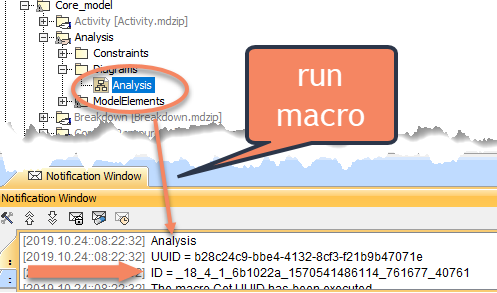
Figure 70 Run “Get UUID” macro to see the ID and the UUID
- Lists
Bulleted lists use standard HTML notation of ul and li tags (see also 4.5 Lists)
the ”;” (all but last) and ”.” (last) must be included.
for example:
<ul><li>first bullet;</li><li>second bullet.</li></ul>
- Fixed hyperlinks
For hyperlinks not auto-generated from the entity and attribute names (see also 4.6 References within the text)
These are contained in <a></a>
They include a <path></path> tag that has the relative path from the Domain model html file to the file, or an http href,
The include the text to be displayed.
For Example:
<a><path>5_main.htm#study</path>Clause 5</a> <a><path>https://www.iso.org</path>iso.org</a>.<br/>
- Example
The following is an example of a formatted description where “Foo” and “Bar” are blocks in the model:
A Foo is a type of Bar that is used as a placeholder. See also <a><path>5_main.htm#study</path>internal links</a>
or <a><path>https://www.iso.org</path>external links</a>. It is has a bulleted list:<br/>
<ul><li>first bullet;</li><li>second bullet.</li></ul>
<note>This is the first note referencing a figure (see following Figure).</note>
<note>This is the second note.</note>
<example>This is the first example referecing the table which is infact an image (see following Table).</example><br>
<figure><name>sys/picturesAnnex/inverseCompositeAggregation.png</name>The title for the figure</figure><br>
<table><name>sys/script/img/tables.png</name>The title for the table</table>
<figuresysml><id>_18_4_1_6b1022a_1570541486114_761677_40761</id>Block Definition Diagram of the Activity CTC</figuresysml>
The following is an example of a property description where “Widget” is a block in the model:
specifies the Widget for the Foo. The value of this attribute need not be specified.
The following shows how the example will look in the standard
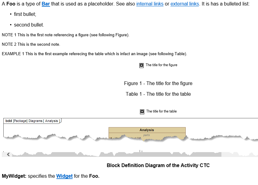
Figure 71 How the example formatted description is displayed in the documentation
Problem and Rationale Comments
Comments that are not to be included in the Standard Documentation should be stereotyped to <<Problem>> or <<Rationale>>.
If the problem comment is added to a diagram the Stereotype can be added at the time the object is created by selecting the “Problem” or “Ratioinale” from the menu. Existing comments can be converted to a “Problem” or “Rationale” by adding the stereotype in the specification window.
Problem and Rationale comments can be added directly to objects (e.g. packages, blocks etc) by adding a comment and then adding the stereotype in the specification window.
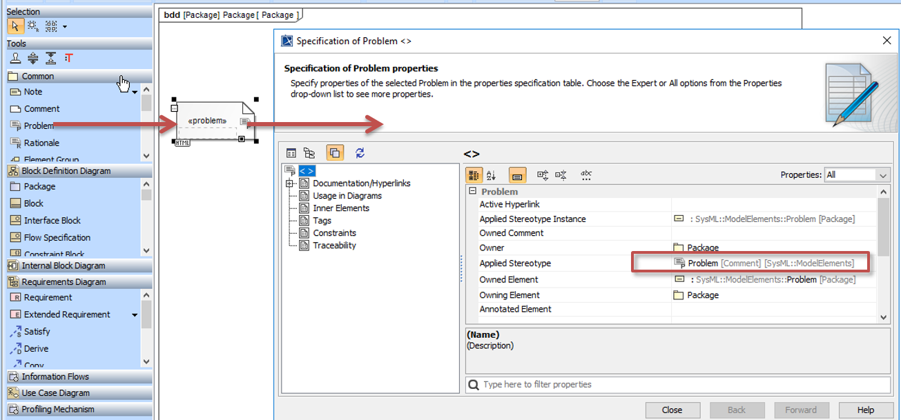
Figure 72 <<Problem>> stereotype on a comment
Block Definition Diagrams - general rules
The following are common rules applicable to all diagrams:
- The diagram has a recommended maximum size of 1300px x 620px (to fit on a typical laptop screen without scrolling) and an absolute maximum size of 4960px x 3508px (A3 print at 300PPI). The following table summarises the recommended sizes for the number of elements assuming landscape.
| Number of objects | Size | 72PPI | 100PPI | 300PPI |
|---|---|---|---|---|
| less than 6 | A5 | 595 x 420 | 827 x 583 | 2480 x 1748 |
| less than 15 | A4 | 842 x 595 | 1170 x 827 | 3508 x 2480 |
| less than 30 | A3 | 1191 x 842 | 2653 x 1170 | 4960 x 3508 |
| reommended | screen | 1300 x 620 |
- A small gap (e.g. one grid square) should be allowed between the edge of the diagram and the elements. (This is because some SysML tools resize the diagram to enforce a gap.)
- The fonts should not be changed from the default, this is controlled by the shared SysML modules (the ISO directives state 8-11pt and the MagicDraw default is 11);
- There should be no 3D shadow and no colour gradient fill.
The following are rules applicable to layout and formatting of elements in Block Definition Diagrams:
- The element or elements that are the subject of the diagram should ideally be in the centre of the diagram and the most obvious on first glance;
- The Block entities should not display their stereotype all other type should be displayed e.g. <<Auxiliary>> (SelectTypes) and <<Value Type>> (Enumerations);
- For the R-G-B to use see BDD Colours;
- Links to related diagrams should be added where useful, by adding the icon - located to minimise disruption to the imact to the diagram. The recommended practise is to wrap the text and position the diagram in the corner of a block.

Figure 73 Links to related diagrams
- Where there are multiple generalization relationships to a single element in a diagram, these should be overlayed at the destination (target).
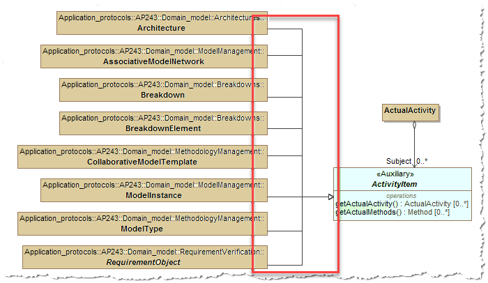
Figure 74 Overlay Destination where multiple links
Layout of “members” diagrams, where there are too many specializations to make the above overlay method impractical, should use an alphabetical grid layout with the Auxiliary displayed surrounding the members.
- Place the members on the diagram
- Select all those that are in a different package from the Auxiliary and change the symbol properties for Show Owner to Above Element Name (from the “All” set of commands)
- Change the symbol properties to enable Wrap Words (from the “All” set of commands)
- Make same size
- Layout - Layout Grid Style
- Place the Auxiliary on the diagram and adjust size so it covers the members
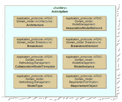
Figure 75 Layout when many members (this example is for illustration, the grid layout is not nessary and the overlay above would be more appropriate)
Entity Types
The modelling steps are:
Abstract Blocks
Abstract blocks are not instantiated, but are used to isolate common features that are then inherited by other blocks.
Auxiliary or “Select Types” Blocks
Tip
These are also known as “Select Types” in the EXPRESS language.
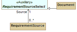
When a part or reference property can have a value of one of several different types of object, then an abstract Auxiliary Block is used. All the applicable types should be made subtypes of this auxiliary.
For example in AP243 an “Assumption” has a reference property “Context” [1], but this item can be of many types. Therefore an auxiliary called “AssumptionContextItem” is created and the applicable items such as Identifiableobject are made subtypes of this auxiliary.
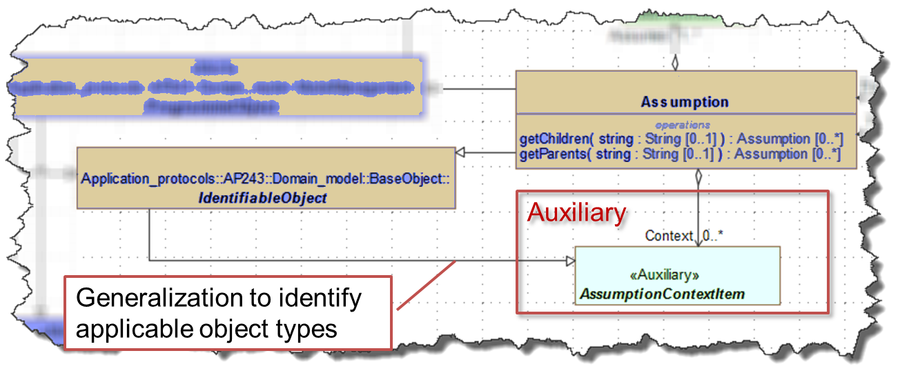
Figure 76 Adding a Auxiliaries (or SelectTypes) for use by Template properties
Optionally the auxiliaries can be stored in a separate package to make them easier to identify as auxiliaries in the model tree.
Often a naming convention is also used to aid identification, though this is only for human understanding. Many of the AP s use the convention of having “Select” or “Item” as the last word in the name.
Note
Auxiliary (in UML) means that this type of class (block) is not directly needed for implementation, therefore they should not have properties. If properties are added they will be ignored in the implementation models (e.g. in the XML schemas).
Abstract blocks (not Auxiliary) can be used to isolate common features of blocks.
It is possible to add operations to Auxiliaries to indicate where common query services are needed. These are treated as implementation hints.
The Steps are:
Create a new block (in auxiliaries package - optional)
Add a name that reflects the intended use (no official convention)
Add description
Open the specification
- set to abstract.
- add stereotype Auxiliary.
Drag onto the block definition diagram and change colour to green - the default (See Colour conventions for STEPLIB diagrams for RGB.)
From the Edit Compartments menu, Stereotypes tab, hide the <<block>> stereotype.
Add generalization from the applicable blocks to the auxiliary.
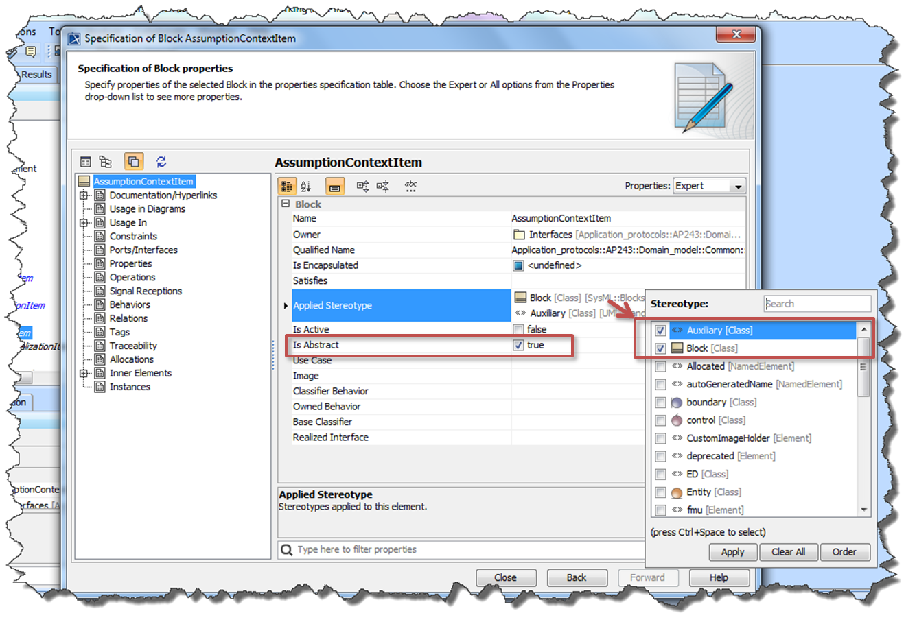
Figure 77 Auxiliaries (or SelectTypes) specification
Enumerations
Todo
Add Enumeration
Add Enumeration Literals for the enumerations, using lower_snake_case [- need to add the rdf - part of he mapping)
Add Base Classifier from the Data Types e.g. String or Real (not sure how to do this as cannot select from tree)
- add the Applied Stereotype for ValueType (this must be done at the end becuase cannot add EnumerationLiterals to a ValueType)
- to add more EnumerationLiterals the ValueType Applied Stereotype must be removed, the enumeration added and the stereotype replaced.
- Add Documentation and/or Reference Data (see Mapping a single Classification for choice of UUID. If not already Reference data, suggest use the UUID of the Enumeration Literal)
- The Reference data for an enumeration can be either reference data classes or named individuals depending on whether it is mapped to Class/ClassSelect or Proxy/ProxyItemSelect respectively
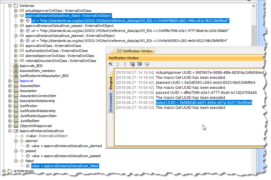
Figure 78 Reference data added to an enumeration.
Properties and Associations
The properties and associations are closely coupled. When creating assocations, the properties are automatically created, and the name of the assocation ends are the same as the property names. The type of assocation imacts the property type. The following lists the type of assocations used and the resultant properties.
The Types of Assocation are:
- Directed Association - Reference Property
- Directed Composite Association - Part Property
- Directed Composite Association - Value Property
- Directed Inverse-Composite Association - Reference Property
- Bi-Directed Association - Reference Property
- Bi-Directed Composite Association Part and Reference Property
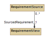
Directed Association - Reference Property
|
 |
 |
|
||
e.g.
|
||
Directed Composite Association - Part Property
|
 |
 |
|
||
e.g.
|
||
Directed Composite Association - Value Property
|
 |
 |
|
||
e.g.
|
||
Directed Inverse-Composite Association - Reference Property
|
 |
 |
|
||
e.g.
|
||
Bi-Directed Association - Reference Property
|
 |
 |
|
||
e.g.
|
||
Bi-Directed Composite Association Part and Reference Property
|
 |
 |
|
||
e.g.
|
||
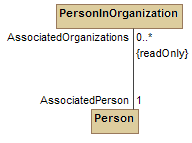
Redefined Properties
A subtype can redefine a property of a supertype. This is usually to change the multiplicity, but may also be to make it a fixed value.
- Double-click on the property to open the Relation Diaglog
- in Redefined Property select the property from the supertype
- Change the multiplicity if needed
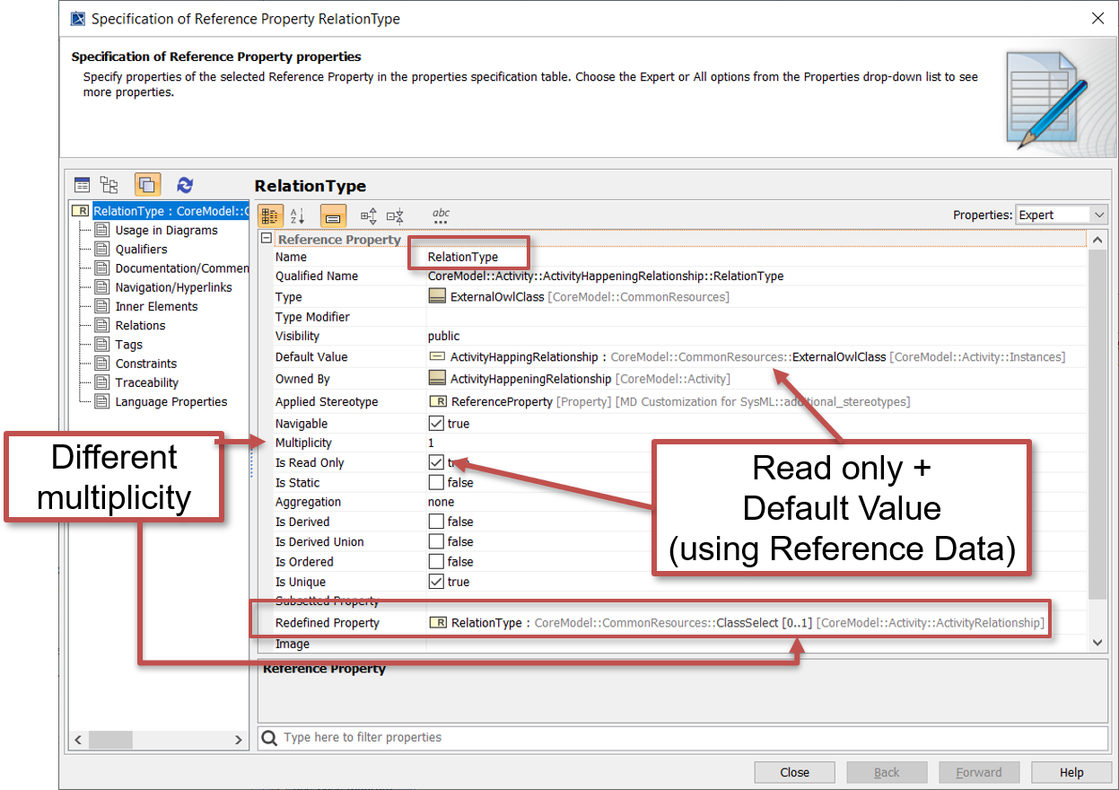
Figure 79 Redefined property set to readonly with a default
If the refeined property is to have a fixed value:
set Is Read Only to true
Assuming the property is of type ClassSelect and the value is in the reference data, then create a new InstanceSpecification (on the Instances BDD diagram)
- Select ExternalOwlClass” for the **Classifier
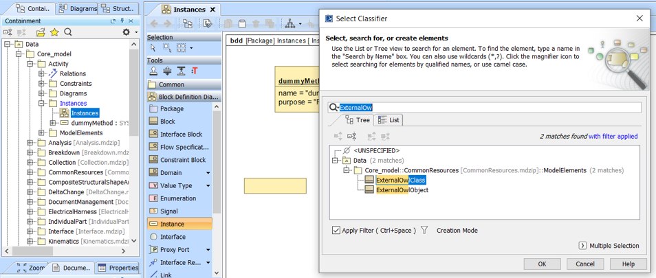
Figure 80 InstanceSpecification of ExternalOwlClass
- Add a suitable name e.g. ActivityHappeningRelationshipClass
- double-click to open the Specification of Instance Specification properties dialog
- Click on the slots
- Select name and Remove Value
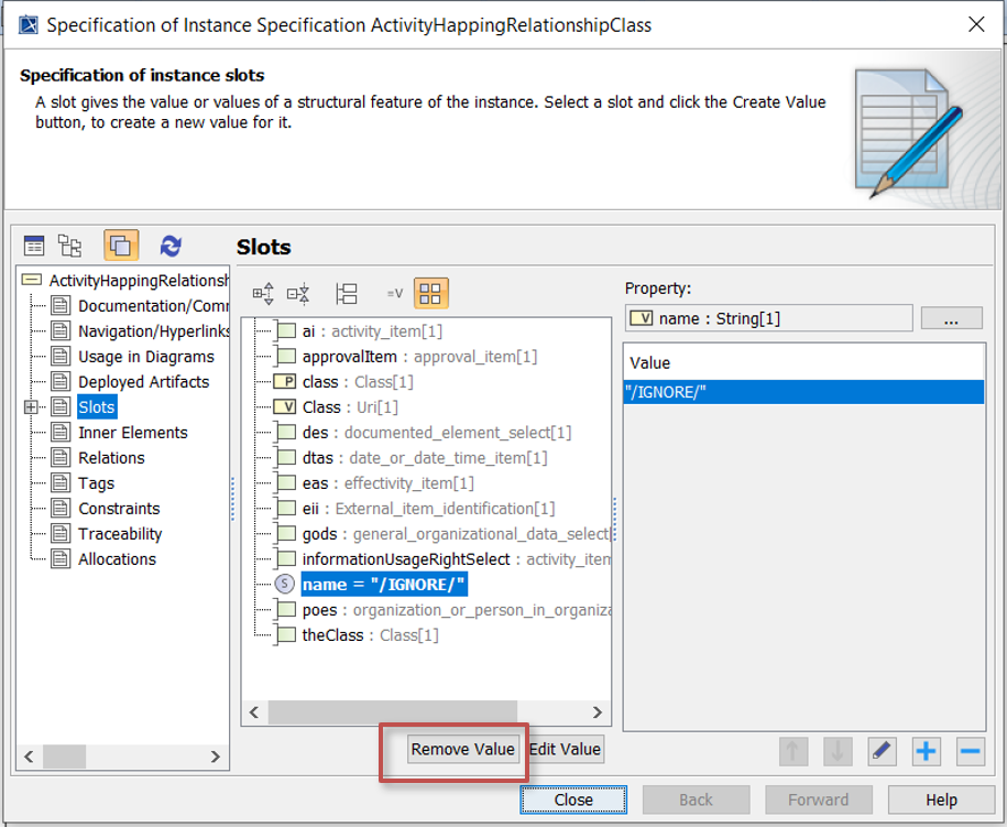
Figure 81 Remove name slot
- Select Class and Create Value
- Select Edit Value and click in the Value property.
- Click on the - icon to remove the 0.0 value
- Click on the + icon and select Literal String
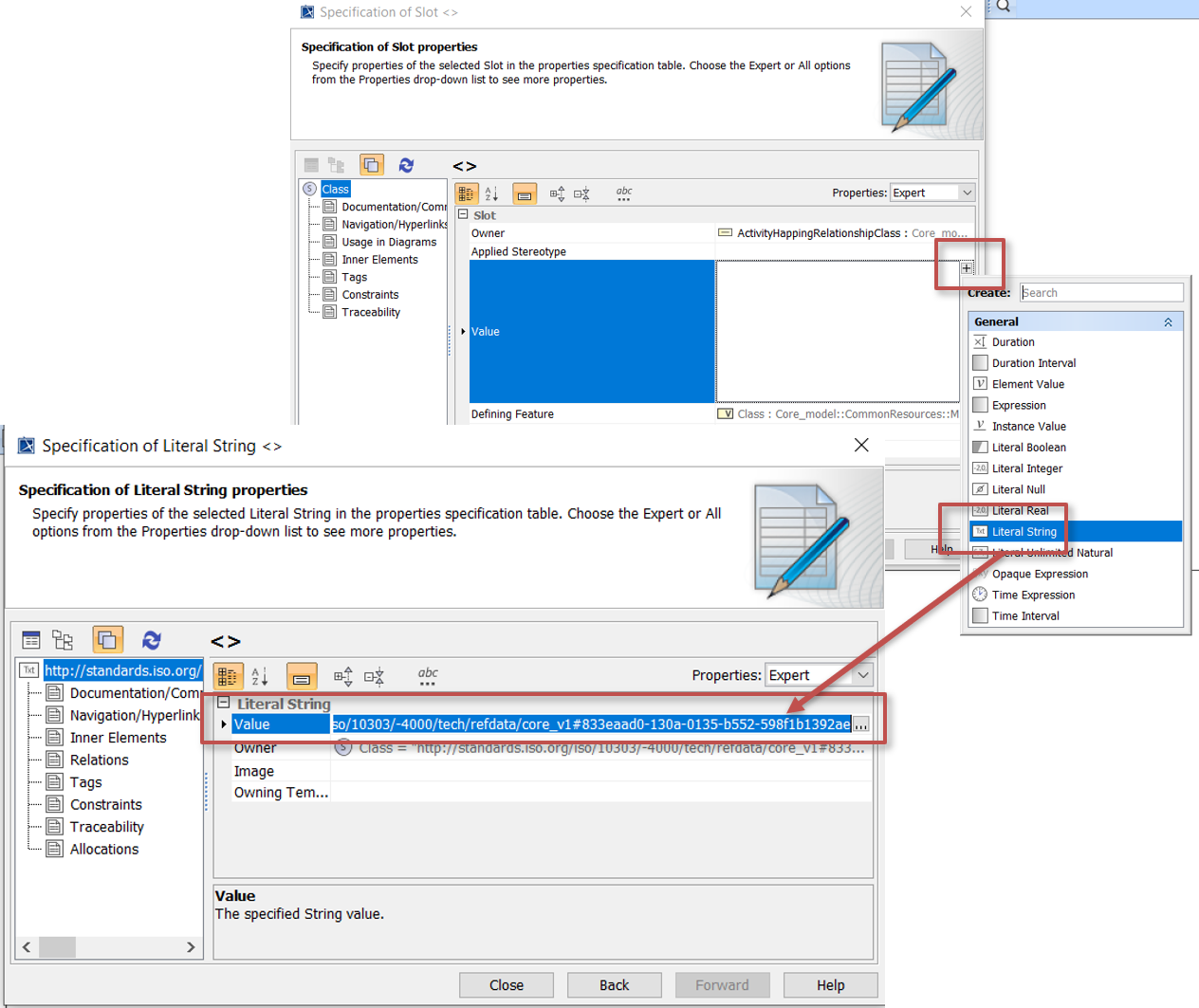
Figure 82 Add the Class slot as a Literal String
- Type in the Reference data URI e.g. for ActivityHappeningRelationship use http://standards.iso.org/iso/10303/-4000/tech/refdata/core_v1#833eaad0-130a-0135-b552-598f1b1392ae
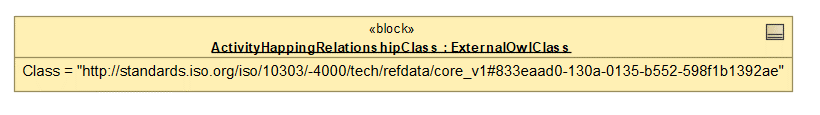
Figure 83 InstanceSpecification with Reference Data URI
Return to the redefined property, and click on ... to the right of Default Value. Then select the new InstanceSpecification
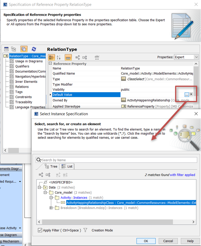
Figure 84 Default Value set to the InstanceSpecification
If the property is shown inside the block, the default value will be shown.
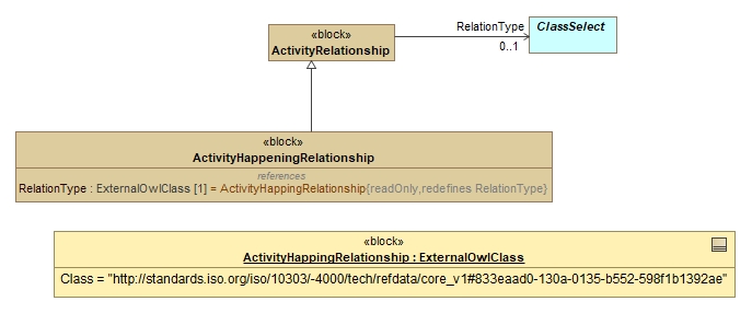
Figure 85 Redefined property set to readonly with a default on diagram
Validation Constraints
The video shows creating a validation constraint on a template. The example is using the Domain Model but it is equally applicable to the other layers.
Todo
display of constraints on BDD - only the name
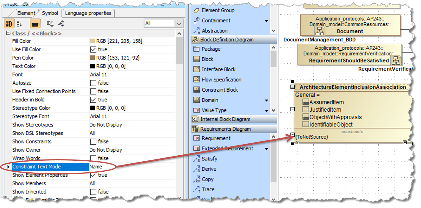
Figure 86 set “Constraint Text mode” to “Name”
Todo
text of this section
Add descrition - it is suggested that this is the same as the “Validation Rule - Error Message”. If more description is needed see How to format descriptions for details
Tip
Add the constraint from the specification window (rather than from the containment tree) as this will automatically set the “Constrained Element” property
Tip
Some Examples
Check that one property value does not equal another property value (Parent[1] Child[1]):
self.Parent <> self.Child
Check for simple circularities in single elements (InheritsFrom[0..1]):
self.InheritsFrom <> self
Check for simple circularities in a collection (InOrganization[0..*]):
self.InOrganization->excludes(self)
Check that a property value is not also in a property collection (Element[0..*] BreakdownOf[1]):
self.Element->forAll(e | self.BreakdownOf <> e)

[Note: syntax error if try to use self.Element->excludes(self.BreakdownOf)]
Check that two collections of property values are mutually exclusive (Manages[0..*] Inputs[0..*]):
self.Manages->forAll(m | self.Inputs->forAll(i | i <> m))
Tip
If the constraint is an “un-computable constraints that cannot, or cannot reasonably, be written in OCL” then the Specification Language should be set to “English”. The constaint is then known as an “Informal Proposition” and will appear as such in the documentation.
For details on validating against the constraints see How to model constraints for use in validation
Query-like services
Todo
text of this section
Current thinking (To Be Agreed) is that the “query-like” services are modelled as operations on the template.
These should then have constraints defined using OCL
C-R-U-D-like services are covered in Domain Model Services.
Section author: Judith Crockford (AP243)