How to model the mapping between the Domain and Core models of STEPLIB

Contents:
Overview
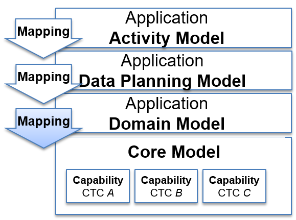
Figure 93 The STEP Architecture
This page uses a simple example to describe how to model the mapping between the Domain and Core models using SysML in MagicDraw 18.4.
Preparation
Important
Prerequists
This assumes that the environment is already set up. See Getting Started - MagicDraw for more details
Common
Diagram Rules
The following are common rules applicable to all diagrams:
- The diagram has a recommended maximum size of 1300px x 620px (to fit on a typical laptop screen without scrolling) and an absolute maximum size of 4960px x 3508px (A3 print at 300PPI). The following table summarises the recommended sizes for the number of elements assuming landscape.
| Number of objects | Size | 72PPI | 100PPI | 300PPI |
|---|---|---|---|---|
| less than 6 | A5 | 595 x 420 | 827 x 583 | 2480 x 1748 |
| less than 15 | A4 | 842 x 595 | 1170 x 827 | 3508 x 2480 |
| less than 30 | A3 | 1191 x 842 | 2653 x 1170 | 4960 x 3508 |
| reommended | screen | 1300 x 620 |
- A small gap (e.g. one grid square) should be allowed between the edge of the diagram and the elements. (This is because some SysML tools resize the diagram to enforce a gap.)
- The fonts should not be changed from the default, this is controlled by the shared SysML modules (the ISO directives state 8-11pt and the MagicDraw default is 11);
- There should be no 3D shadow and no colour gradient fill.
The following are rules applicable to layout and formatting of elements in Parametric Diagrams:
- Domain object properties are conventionally placed on the left side of the diagram
- The private property typed to “target” Core object is conventionally placed on the extreme right side of the diagram
- The “target” flow port is conventionally placed on the extreme right-hand edge of the diagram
Colours
For the R-G-B to use for the Domain Model and Core Model entities, and for constraints and flow ports, see Colour conventions for STEPLIB diagrams.
Problem and Rationale Comments
Comments that are not to be included in the Standard Documentation should be stereotyped to <<Problem>> or <<Rationale>>.
If the problem comment is added to a diagram the Stereotype can be added at the time the object is created by selecting the “Problem” or “Ratioinale” from the menu. Existing comments can be converted to a “Problem” or “Rationale” by adding the stereotype in the specification window.
Problem and Rationale comments can be added directly to objects (e.g. packages, blocks etc) by adding a comment and then adding the stereotype in the specification window.
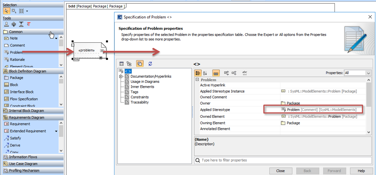
Figure 94 <<Problem>> stereotype on a comment
Step by Step guide
The modelling steps are:
Setup the diagram
The first step is to add a new SysML Parametric Diagram to the Block/template, and select the local properties. The inherited properties should be mapped as part of their owning block/template. See also video in Adding elements from the Core.
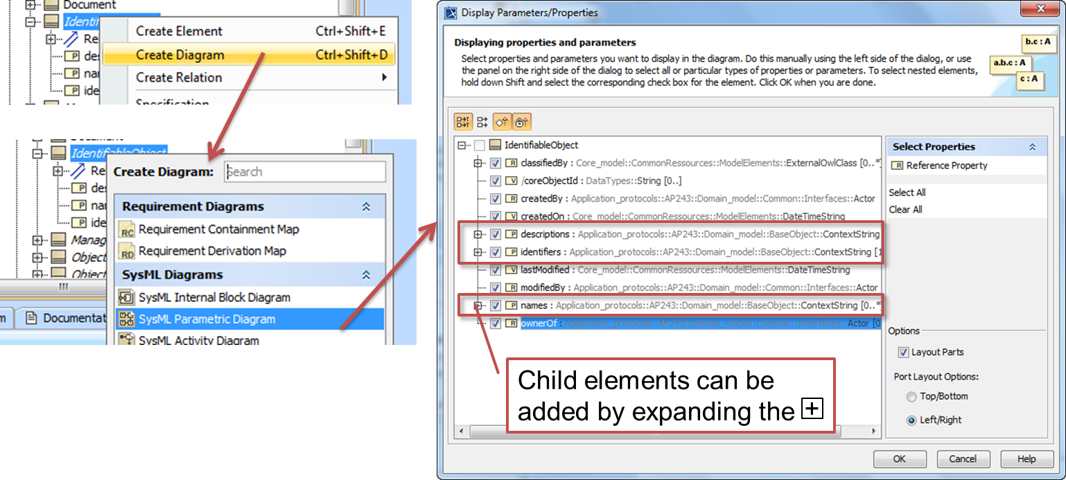
Figure 95 Create a new diagram and add the local properties
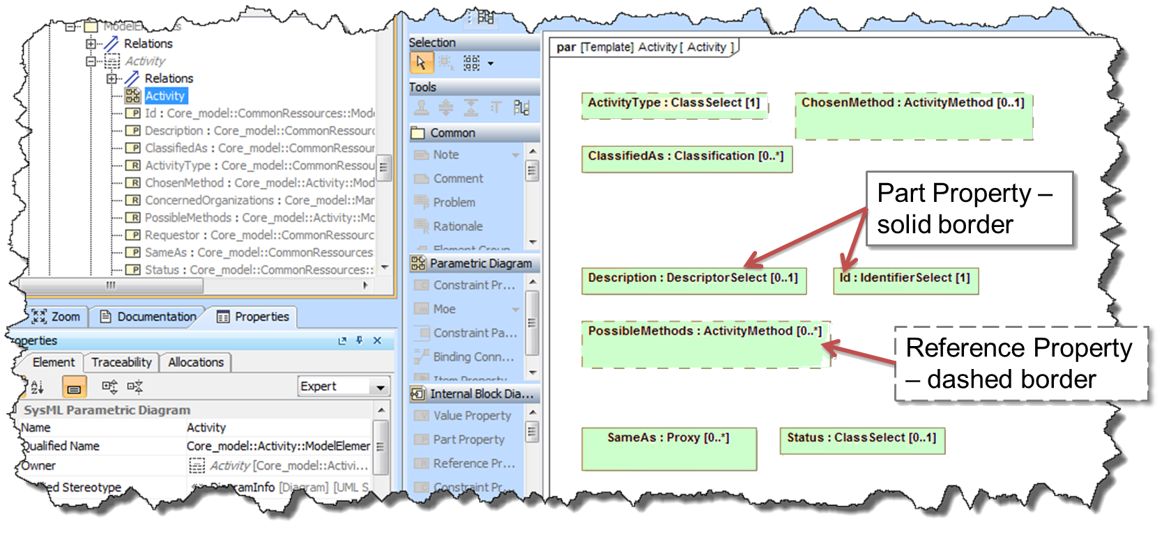
Figure 96 Selected Properties are shown on the diagram
Adding elements from the Core
The block and its properties are mapped to elements from the Core (or other AP). These are added to the block as private part properties. (see Naming Conventions and Colour conventions for STEPLIB diagrams)
Todo
protected rather than private on the superclass (TBC)
Warning
The colours convention has been updated since this video was created. See Colour conventions for STEPLIB diagrams for the latest colours.
The video shows creating a new parametric diagram adding a private property using a type from the core, and mapping it to a property of the block.
Todo
steps for this section
Adding flow-out ports
Flow-out ports are used to expose internal (private) structure of the block/template that are needed by other blocks/templates. The type and cardinality of these ports are declared to ensure that connections defined in other templates are appropriate.
Tip
It is recommended that only the ports that are really needed are exposed. One way to achieve this is to add the ports when they are found to be needed rather than anticipate the need.
Tip
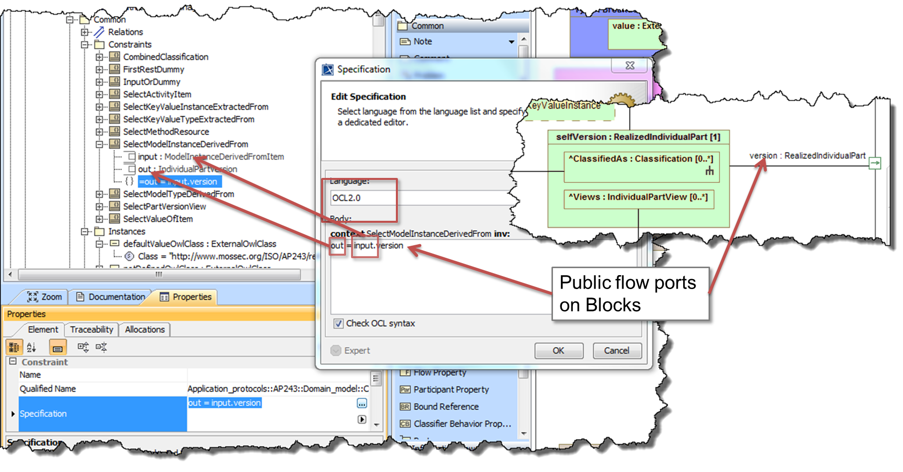
To make the “Select” constraints simpler, it is recommended that a naming convention is applied to the flow ports. For example in AP243, the following convention was used:
- item for the main object e.g. Document, Part, Activity, Collection, Association, etc
- version for when there is also a version-like port e.g. DocumentVersion, RealizedIndividualPart CollectionVersion etc
- view for when there is also a view-like port e.g. PartView, IndividualPartView, RequirementView, CollectionView etc
The constraint can then simply be “out = input.version”
(see Naming Conventions)
Todo
steps for this section
Mapping a single Classification
This shows how to add a mapping for a single classification. For more complex, combined and enumeration classification mapping see Mapping a combined Classification
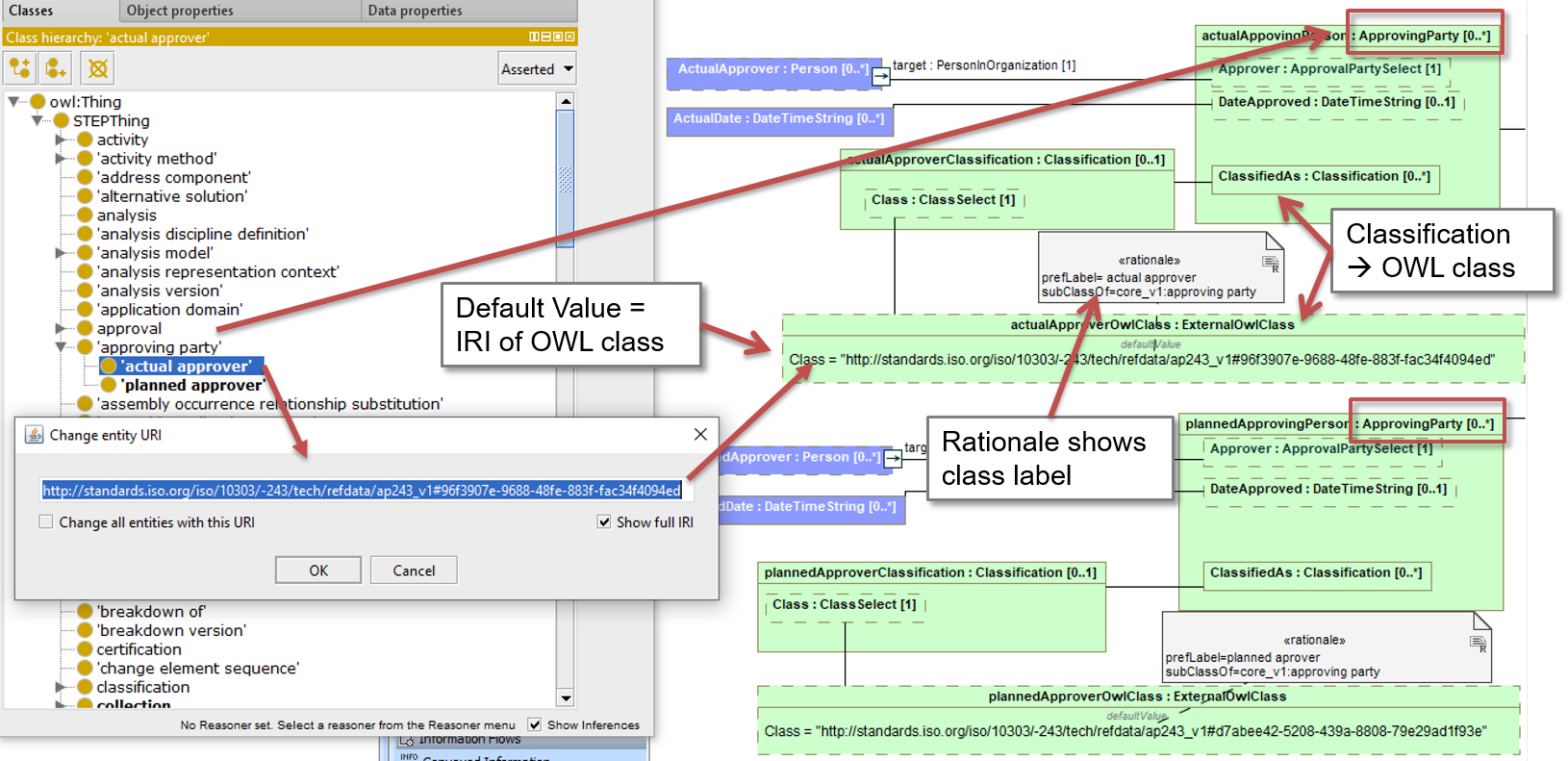
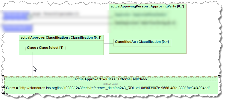
The mapping uses Reference Data Classes from the Reference data that is set as the default value of an instance specification . The selected OWL class should be a sub class of the block to which the classification is mapped. In the following example, the classification is mapped to the Core model block ApprovingParty, and therefore the selected OWL class is a sub class of “approving party”.
Classification naming convention
The suggested convention is as follows:
- (private) Part Property of type Classification
- Prefix lowerCamelCase for classification string
- Suffix Classification
- e.g. modelTypeClassification
- Reference Property and Instance Specification of type ExternalOwlClass
- Prefix lowerCamelCase for classification string
- Suffix OwlClass
- e.g. modelTypeOwlClass
- contraint property
- lowerCamelCase version of Constraint Block
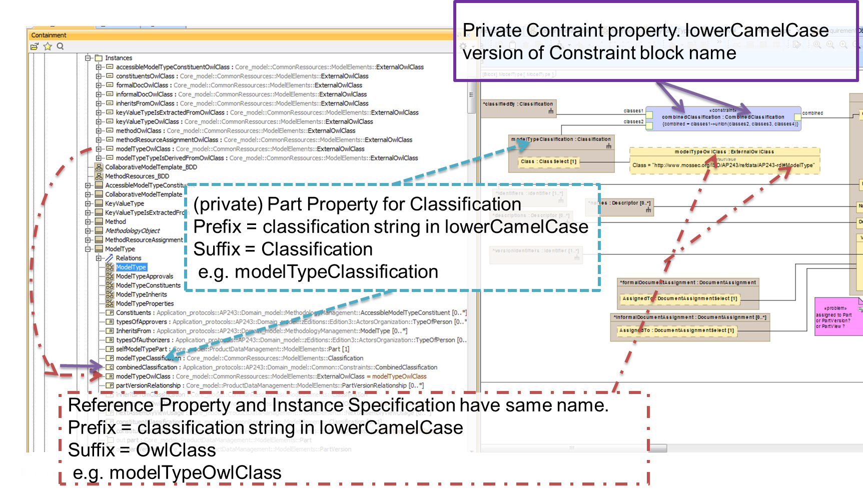
Figure 97 Naming convention for elements used in mapping classifications
Video

Steps
The steps are:
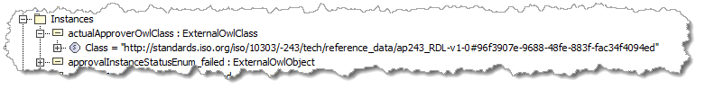
Create a new Instance Specification in the Instances Package (create the package if needed)
Set the Classifier to ExternalOWLClass from Core_model::CommonRessources::ModelElements
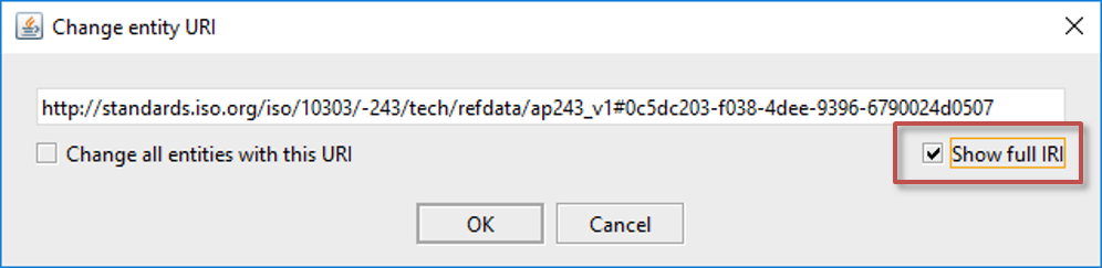
- Set the Slot value for the Class property to a Literal String with the value set to the IRI of the OWL Class. The options for the IRI are:
- IRI copy functionality in Protégé (ctrl-U) can be used to copy the IRI to paste into the slot value (when the STEPlib RDL is setup). Note: the class can be in the AP RDL or the Core Model RDL
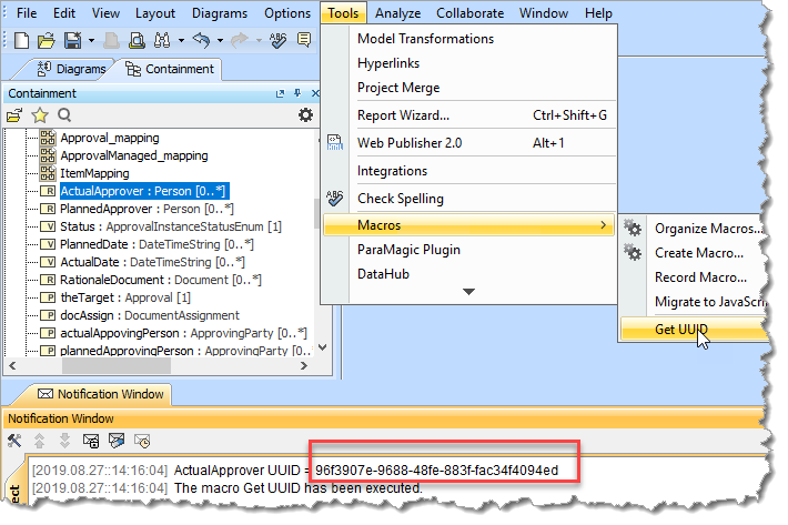
- Use the UUID for a selected object. A macro has been written which will print the UUID of the selected object to the notifications window. If this macro is not already loaded into MagicDraw it can be found in STEPlib/utils/MagicDraw/getUUIDmacro.js. Note: this will then need to be added as an OWL class to the AP RDL
- Create an arbitrary IRI (while waiting for AP RDL to be set up) Note: this will then need to be added as an OWL class to the AP RDL
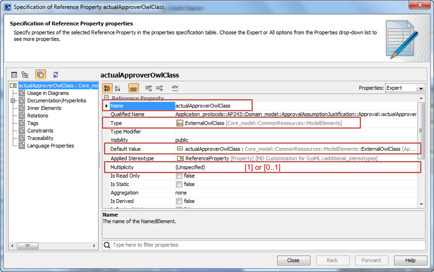
- Add a new Reference Property to the parametric diagram for the block
- set the type to ExternalOWLClass
- set the Default Value to the Instance Specification above
- set the multiplicity ([1] or [0..1] depending on what it is connected to)
Todo
visibility = public - TBC
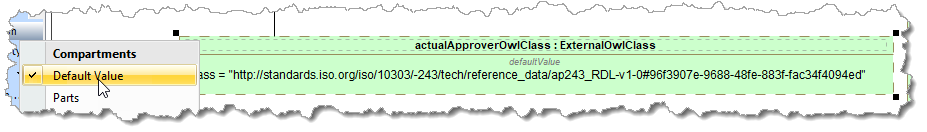
- In the diagram, display Compartment for the Default Value
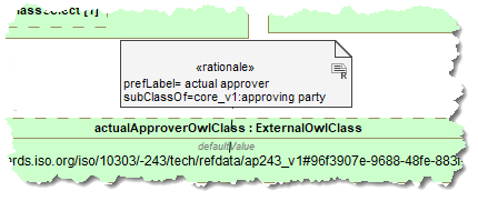
- Add a Rationale comment (comment stereotyped to rationale) showing the Class Preferred label (skos:preflabel) mandatory property of the class and of the Class Subclass (rdfs:subclassof) mandatory property.
- Add a new Part Property to the parametric diagram for the block
- set the type to Classification
- set the Visibility to Private
- set the multiplicity. This should be either [1] for compulsory objects or [0..1] for optional.
- display the Class property
Create a Binding Connector from reference property to the Classification.Class
- Create a Binding Connector from Classification part property to the Classification in the core element
Mapping a combined Classification
Warning
The colours and naming convention has been updated since this video was created. See Colour conventions for STEPLIB diagrams for the latest colours and Naming Conventions for the latest naming.
Classification naming convention
The suggested convention is as follows:
- (private) Part Property of type Classification
- Prefix lowerCamelCase for classification string
- Suffix Classification
- e.g. modelTypeClassification
- Reference Property and Instance Specification of type ExternalOwlClass
- Prefix lowerCamelCase for classification string
- Suffix OwlClass
- e.g. modelTypeOwlClass
- contraint property
- lowerCamelCase version of Constraint Block
Figure 98 Naming convention for elements used in mapping classifications
Enumeration naming convention
The suggested convention is as follows:
- (private) Part Property of type Classification
- Prefix lowerCamelCase for classification string
- Suffix Classification
- e.g. modelTypeClassification
- Reference Property and Instance Specification of type ExternalOwlClass
- Prefix lowerCamelCase for classification string
- Suffix OwlClass
- e.g. modelTypeOwlClass
- contraint property
- lowerCamelCase version of Constraint Block
Figure 99 Naming convention for elements used in mapping classifications
Video
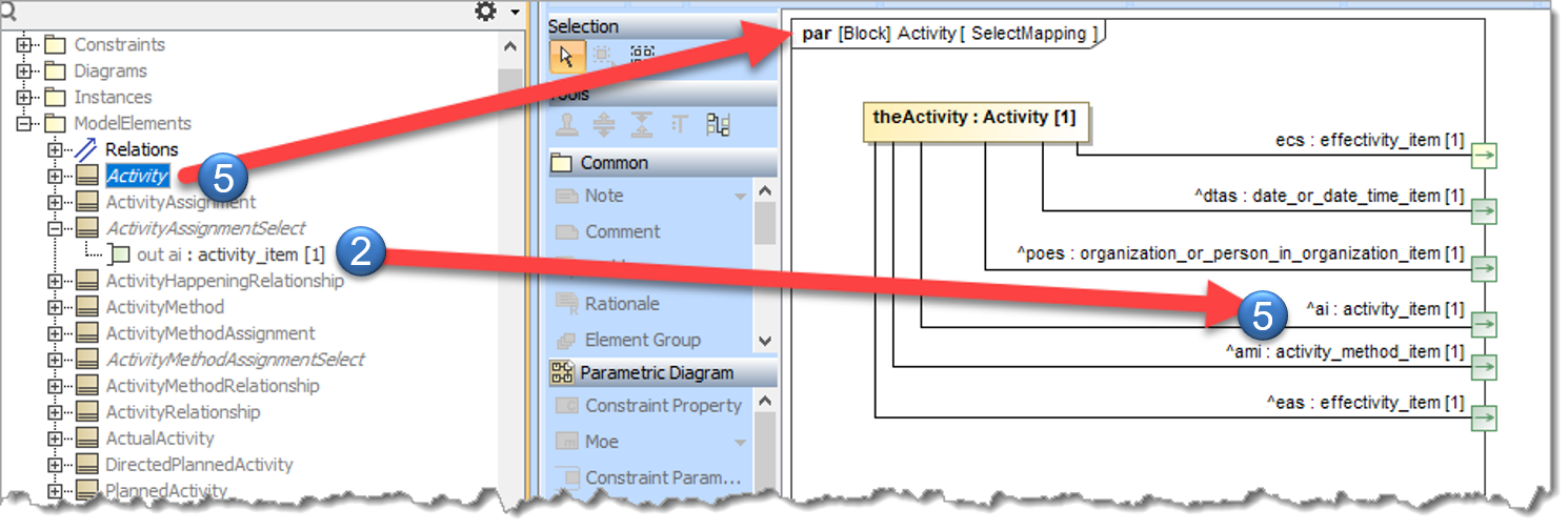
Select Mapping
See also How to create a select mapping
Process for a given “source select” e.g. “ActivityAssignmentSelect”:
decide on the “target select” to map to.
Add a flow port to the “source select”, typed to the “target select” and named with the first letters of the words of the “target select” (or similar to get unique name)
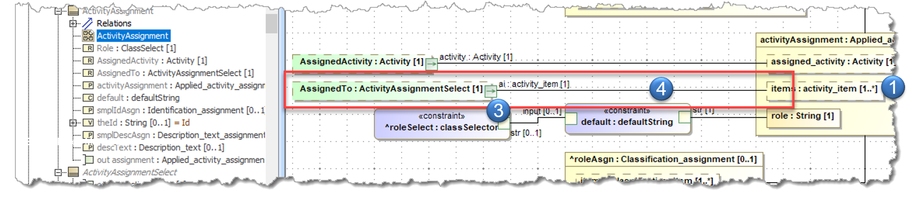
In the mapping diagrams, add the flow port to the property that is typed to the source select.
bind this to the property in the target that is typed to the “target select”
for each block that is a specialization of the “source Select”,
- create a diagram for the select mapping (if it does not already exist)
- add the flow port to this diagram
- drag the appropriate private (mapping) property onto the diagram and create a binding connector to the flow port.
if there are no private properties that can have binding connectors to the flow port, then either one must be created, or the block cannot be a specialization of the “source select”.
Todo
For 6. above, is it possible to have more flow ports of different types for a source select and then use a constraint for when there is more than one mapping?
Adding Contraints
Create a Simple Constraint
Todo
Note: this should actually be done using a select mapping
This example is creating a constraint block for a “select type”, so it needs two constraint parameters, the input of the Domain Model “select type” and an output typed to the appropriate object from Core Model. The contraint is then a if-then-else conditional.
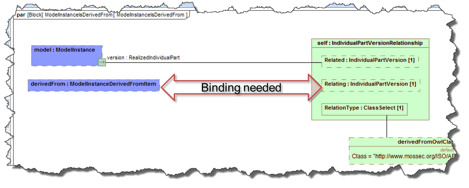
Figure 100 Example for using a constraint
Video
Todo
update to add “is readonly” to the output ports
Steps
The steps are:
- Search to see if there is an existing Constraint Block for what is needed.
- if yes, then skip these steps and go on to Using a Constraint
Create a “Constraints” package if it does not already exist
- Create a new Constraint Block
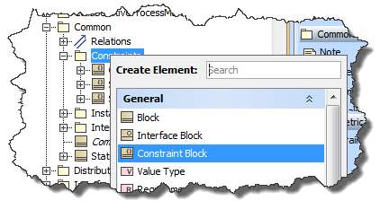
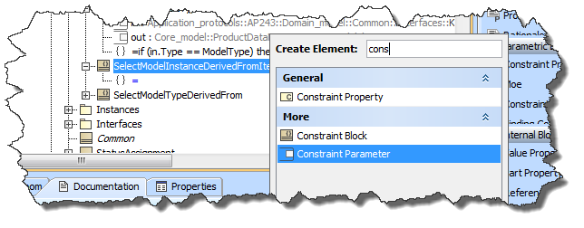
- Add Constraint Parameters
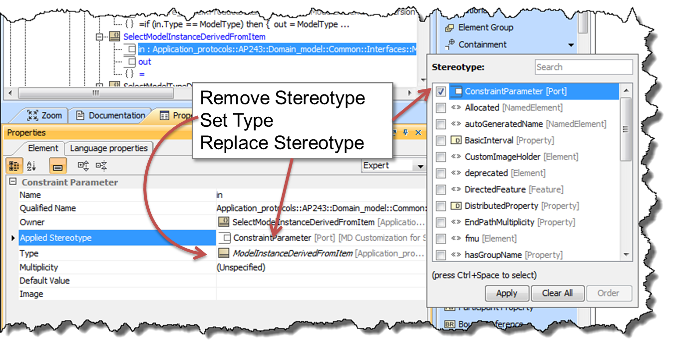
- Set the type for each Constraint Parameter as follows:
- remove constraint parameter stereotype
- set the type needed
- reset constraint parameter stereotype
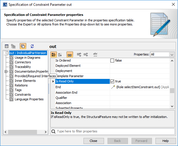
For the output Constraint Parameters set the Is Read Only to true
- Edit the specification “{}”, using Language of OCL2.0
Using a Constraint
Video
Important
This video does not hide the constraint on the constraint property.
See the detailed steps for the correct display.
Steps
The steps are:
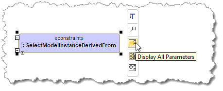
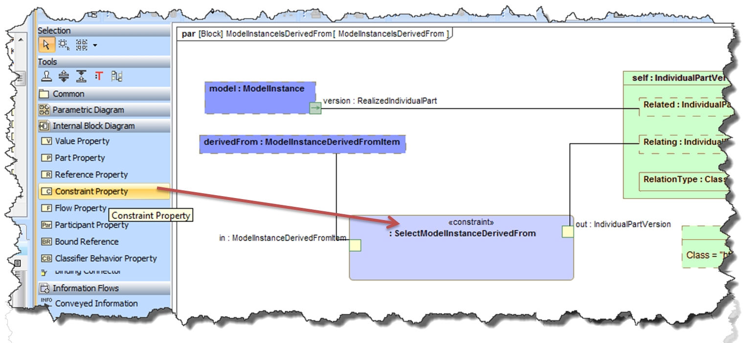
Add a new Constraint Property to the Parametric Diagram
- Specify the Type to be an existing Constraint Block
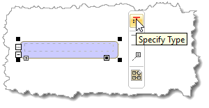
- Display the Parameters
Add Binding Connectors between the parameters and elements on the diagram
Optionally display the parameter types
Complex constraints
Todo
see examples of describeSelector or idSelector in the core
Missing mandatory properties
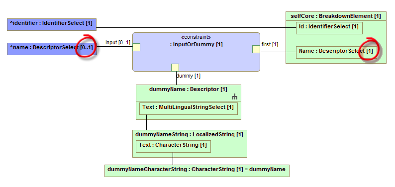
In some cases the template in the lower layer has compulsory properties that are not present in the upper layer. When this happens a dummy entity must be created.
In the below example it can be seen that the property “name” in the upper layer has multiplicity of [0..1] whereas the lower layer has [1]. This means that sometimes the upper layer will not have a name. This is resolved by creating a dummyName and using a constraint that will use this if the input is not provided. This is illustrated below.
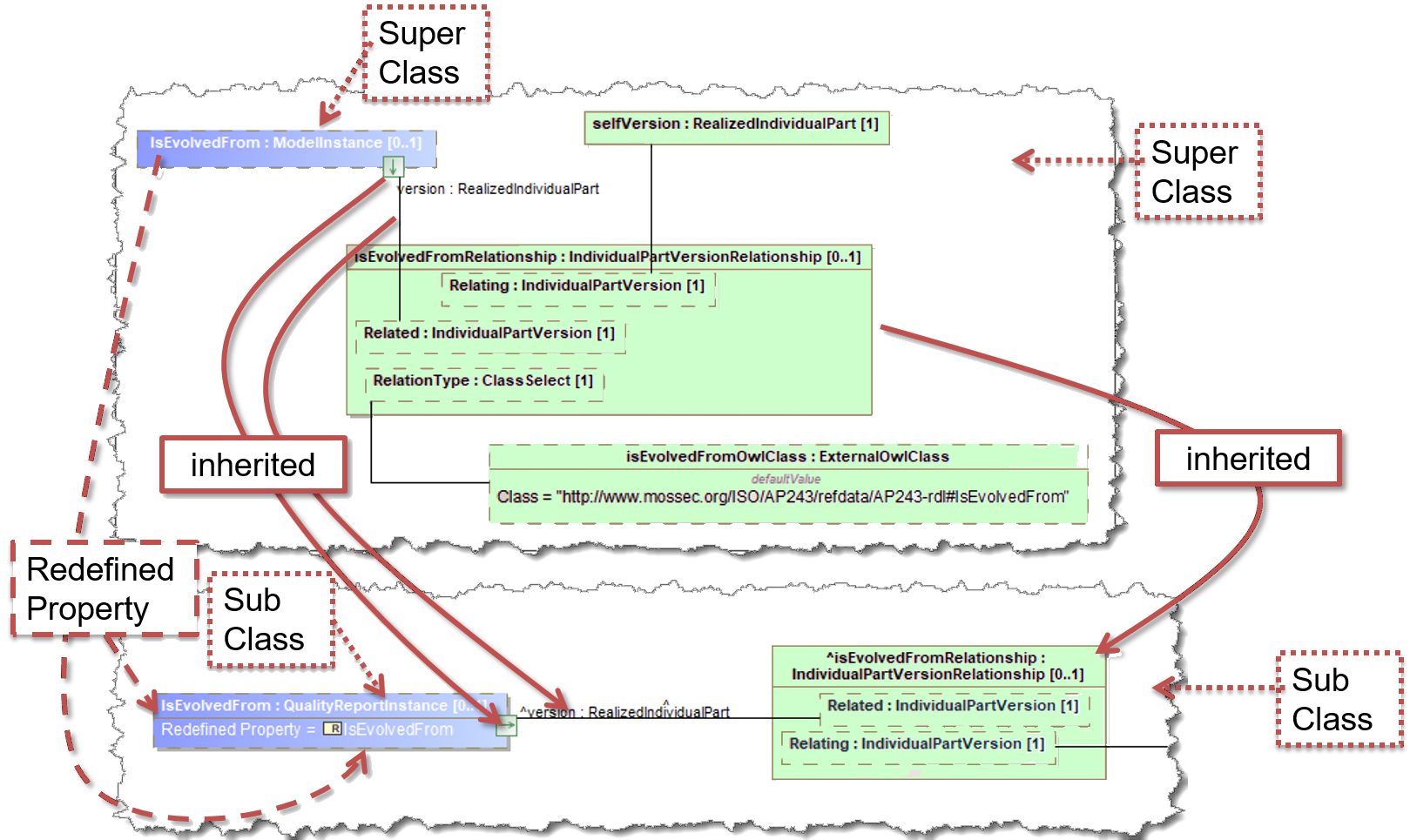
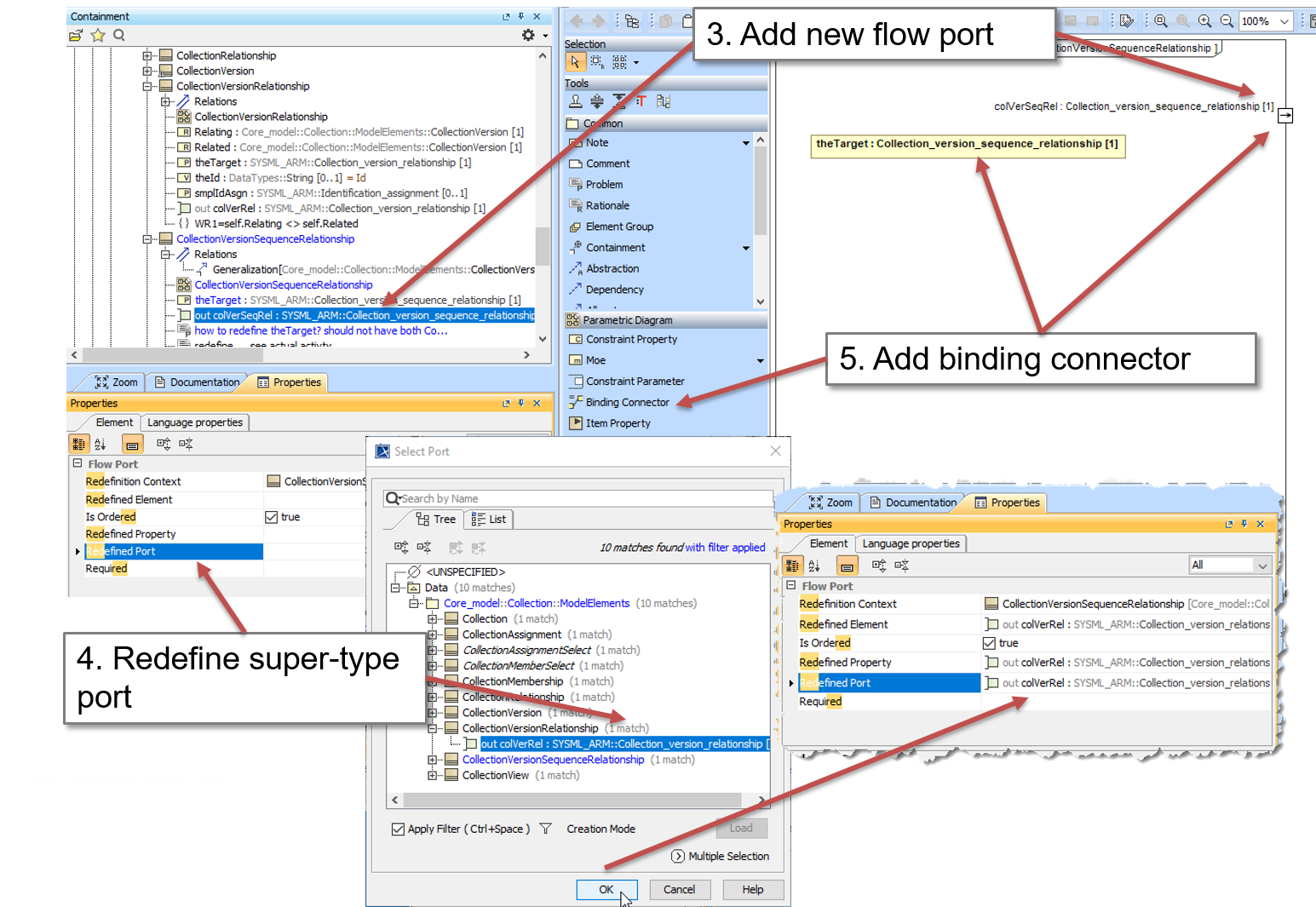
Redefined properties and inherited mappings
Todo
Should just be able to use the inherited. Assumes the redefined are sub-types of the objects they are redefining. See also Redefined Properties
The steps are:
Drag the inherited part property onto the diagram
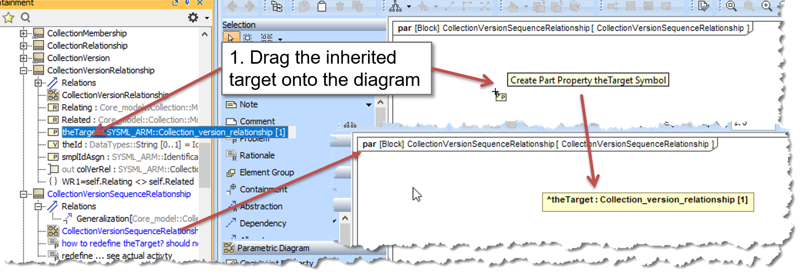
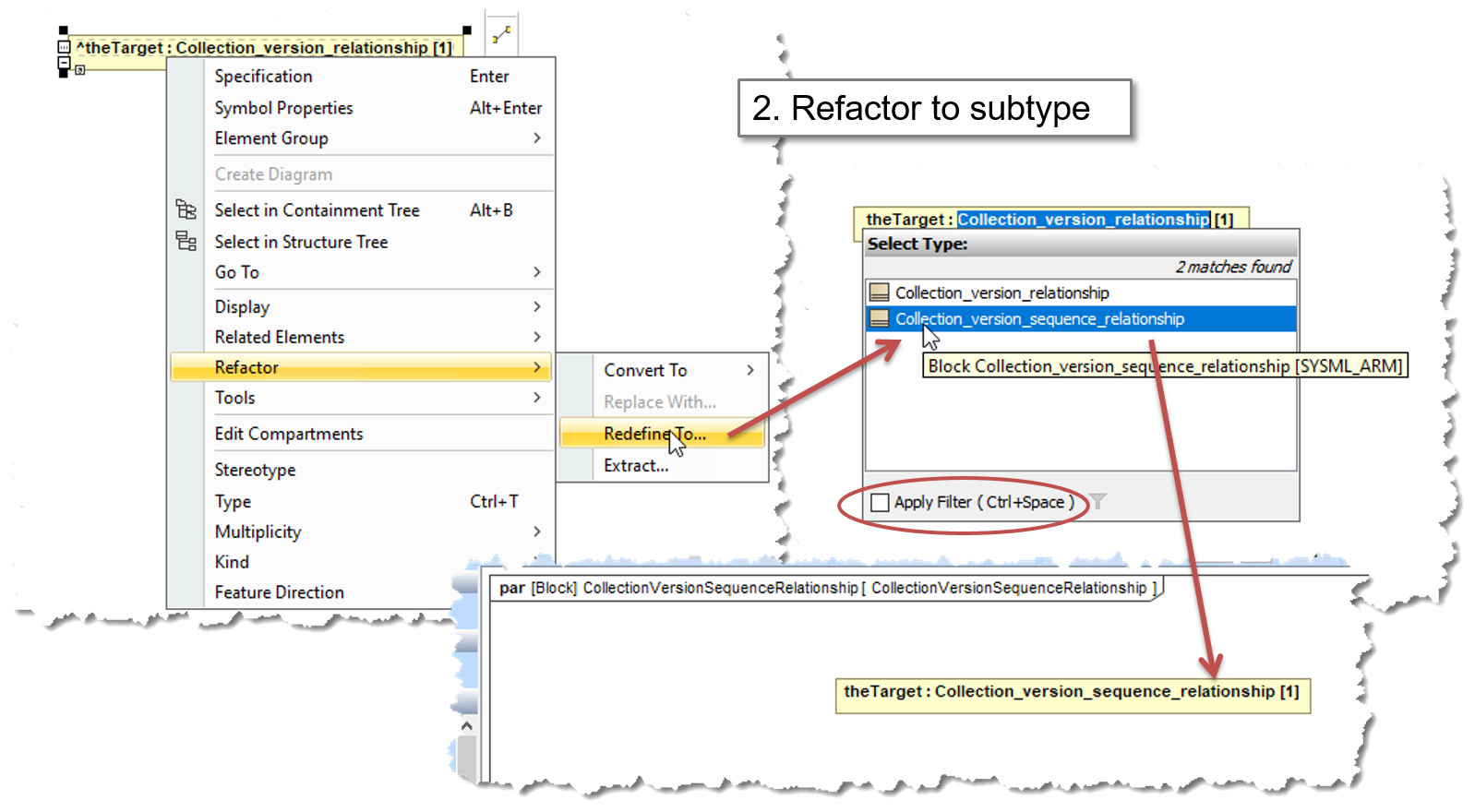
Refactor > Redefine To and select the subtype
Add a new flow port typed to subtype
Select Redefined Port and select the supertype port.
Add a binding connector
protected rather than private on the superclass (TBC)
(from https://trello.com/c/ajMU2USq/100-n-standing-doc-method-to-map-subtypes-using-supertype-mapping)
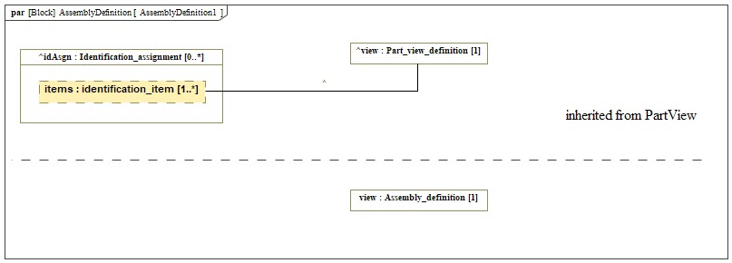
Figure 101 Inherited showing protected and refactor->redefine
PS: Dragged the protected part property view from PartView onto the parametric diagram for AssemblyView. (JC - I do this using the Display parameters/properties as it is safer; can see all inherited so can do multiple at same time )
Right click->Refactor->Redefine to then selected Assembly_definition
This creates the redefined view part in the current mapping
Option 1 (display the original binding connector on the diagram):
- use text box and horizontal separator to add some visual separation to the diagram
- drag the Protected part property view from PartView onto the diagram again (this time placing it in the inherited section of the diagram)
- drag the Protected part property idAsgn from PartView into the inherited section of the diagram.
- select ^idAsgn right click->Display Parts, then selected items from the list. This then automatically showed the binding connector created in the PartView parametric diagram
Option 2 (see the binding connector to the redefined object):
- Create a new binding connector
- add a name to the original binding connect (so it can be found in the tree, any text will do)
- set the redefined connector in the new, to the orginal
- remove the name from the original
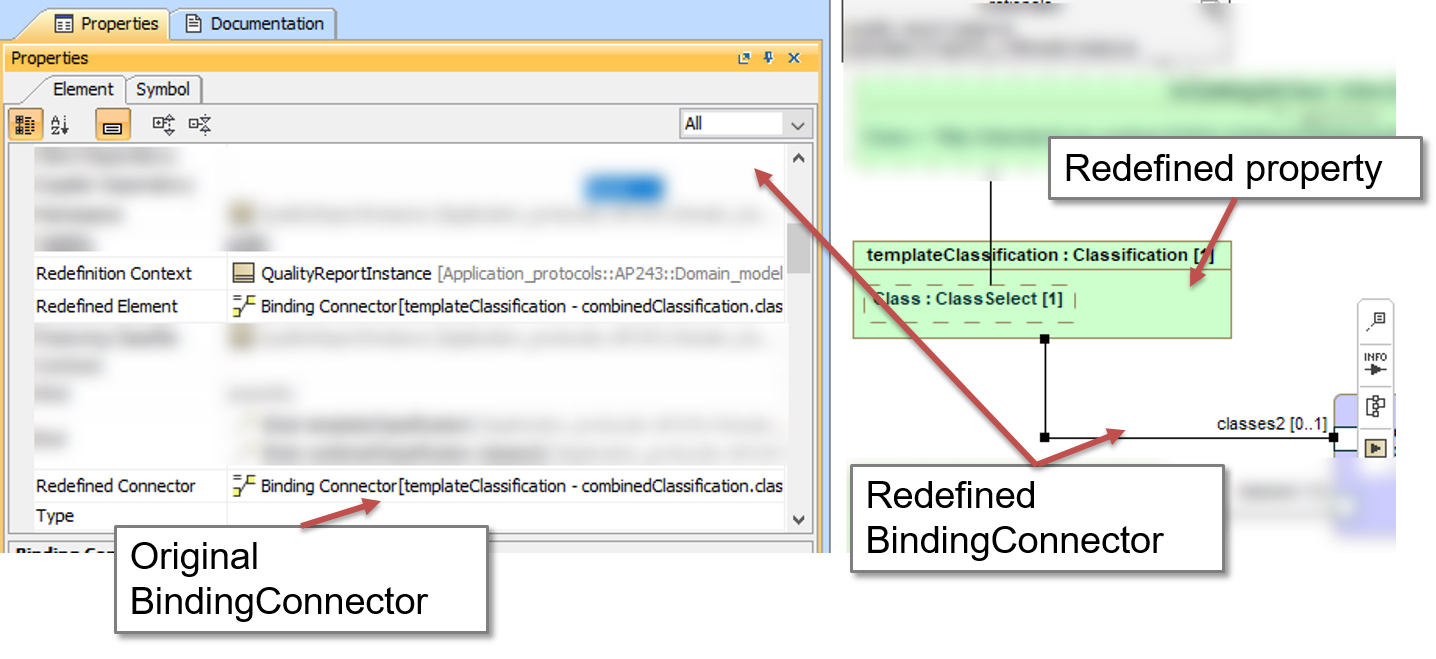
Figure 102 Inherited redefined binding connector
The advantage of this approach is:
- We can (with some effort!) show the mapping inherited from the supertype in the parametric diagram of the subtype
- We can show protected properties from the supertype that have been redefined (however there is no graphical symbol to indicate the redefinition relationship between two properties) and explicitly show any mappings required at the subtype level that are not required at the supertype level.
Patterns
Patterns are used to show how a “concept” in one level is represented by objects in the same level.
Todo
text for this section
Notes from Trello
Our understanding:
- a template/pattern use parametric diag with domain elements inside
- the template/pattern tells you that the set of domain elements inside has to be instantiated as described in the parametric (relationship and values
- it can avoids, for instance, 2 way of setting property information to an object (either prop assignment , either using owned attributes, etc.), which add a constraint to the model to better use it
- Each template is a block (a kind of concept, with a parametric), but is is NOT an ENTITY, which is NOT mapped to the lower level (eg ARM), but each Domain Objects are, of course are mapped to the lower level => let’s not mix Template and Parametric Mapping !
- the Template’s attributes (properties in the left in the Parametric) are the main information to manage and store/assign (old attributes from original ENTITY)
Example: ContentProperty has a description, which is represented by additional descriptions being associated with the DocumentDefinition or File, these extra descriptions being classified as ContentDescriptions. Similarly the DetailLevel of the ContentProperty is represented as additional descriptions classified as DetailedLevel being associated with the target object.
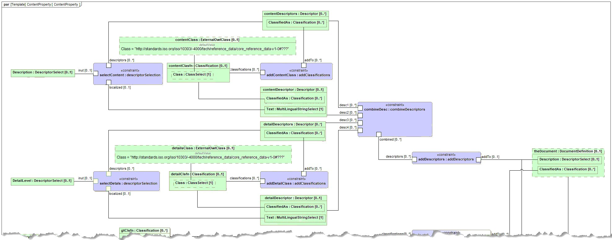
Figure 103 Exmaple for ContentProperty
Section author: Judith Crockford (AP243)