How to model the Application Activity Model of STEPLIB

Contents:
Overview
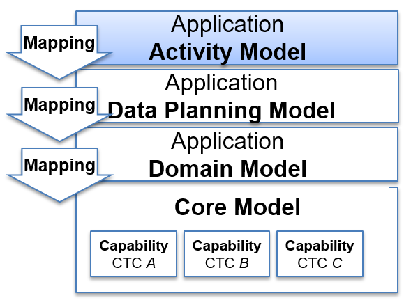
Figure 48 The STEP Architecture
This page uses a simple example to describe how to model the the Application Activity Model using SysML in MagicDraw 18.4.
The Application Activity Model of an application protocol is a Functional model to identify the information flows of interest to be supported by the application protocol.
Preparation
This assumes that the environment is already set up. See Getting Started - MagicDraw for more details. Also that there is an Activity_Model node, Conceptual_Model node and the Activity profile is included as shown below.
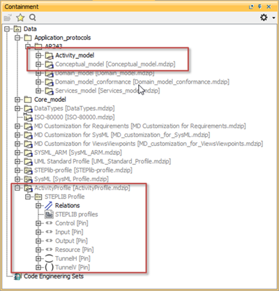
Figure 49 Application Activity Model starting point
General Rules
Rules:
Top level A-0
The model shall contain a A-0 context diagram, which contains only one StructuredActivityNode.
Only one flow out of a pin
If two flows are needed from a single pin, then a fork should be used to split the flow.
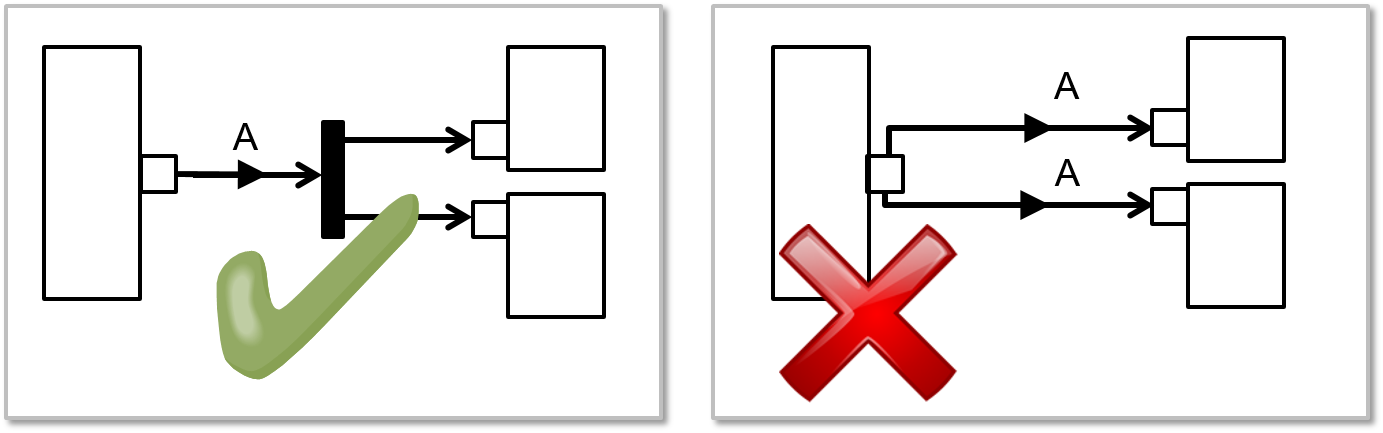
Figure 50 Use Fork so only one flow out of a pin
Only one flow into a pin
If two flows are needed into a single pin, then a merge should be used.
Figure 51 Use merge so only one flow into a pin
Conveyed information conventions
The conventions for conveyed information are as follows:
The flow from a pin must have conveyed information (A) unless (B) it is connected to a merge where all the inputs to be merged are assumed to be the same, in which case it is assumed to have the same conveyed information as the output from the merge
The flow from a fork only needs conveyed information if (C) it is division of the input flow conveyed information, otherwise (D) it is assumed to have the same conveyed information as the input to the fork
If the flows into a merge have:
- same conveyed information (E), the output flow not need conveyed information, it is assumed to have the same conveyed information as the input to the merge
- different conveyed information, the output flow must have either a single conveyed information that is an aggregation the input conveyed information (F), or all the input flow conveyed information added to the output flow conveyed information (G).
- no conveyed information, the output flow must have conveyed information (H), and the input flows are assumed to also have this conveyed information
The preferred use for merge and fork is for a single merge with multiple inputs rather than a series of merge each merging two inputs, similarly for a single fork with multiple outputs. However if the non-preferred layout is used for cosmetic reasons, the above conventions are recursive.
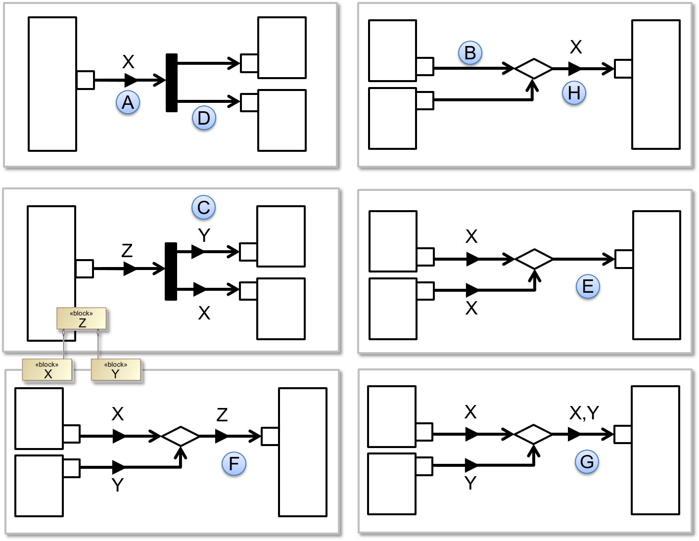
Figure 52 Convention for conveyed information
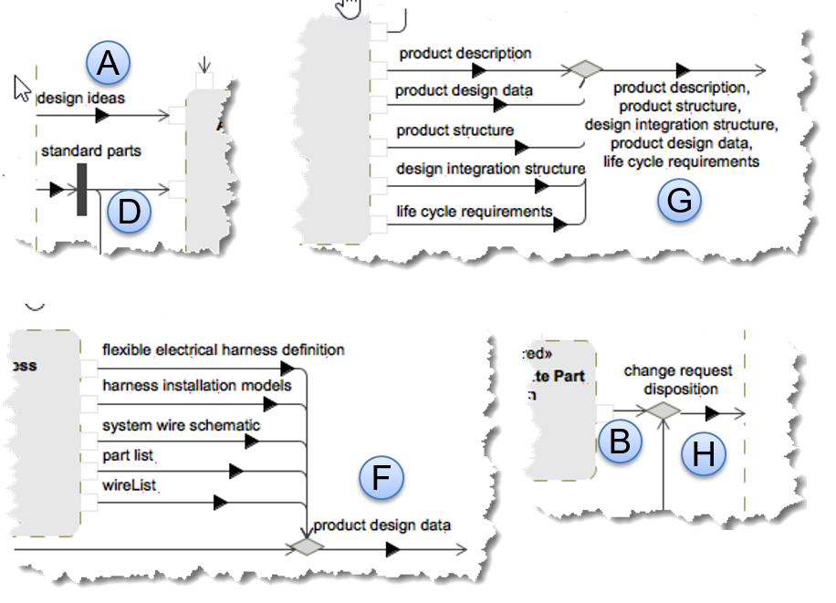
Figure 53 Examples for conveyed information from AP242
No more than 9 activities per level
For readability, there should be no more than nine activities per level. If more are needed it is an indication that additional levels should be inserted.
This is also related to the Naming Convention.
Naming Convention
The general convention for StructuredActivityNode is for a level prefix and then space separated name with each word capitalized. e.g. “A2 Manage Product Development Project”.
Each level prefix is as follows:
- The top level Activity and it’s StructuredActivityNode should both be called A-0 APname. These are the context for the AAM
- There should be one Activity representing the AP, this should start with A0
- Children of A0 should be A1, A2, A3 etc
- Children of these are subsequent levels start with their parent prefix and append a sequential number (e.g. children of A3 are A31 A32 A33 etc, children of A33 are A331 A332 A333 etc)
- StructuredActivityNode names and concept names shall not consist solely of the following words: function, activity, process, input, output, control or mechanism.
This is illustrated in Figure 54 below.
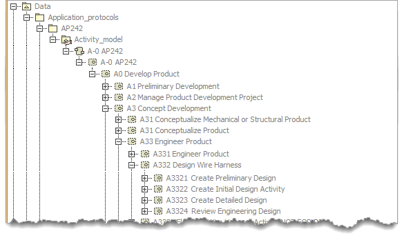
Figure 54 Example from AP242ed2 showing naming convention
There is no strict nameing convention for the pins except that they should start with lowercase.
The Activity Diagrams should have the same name as the StructuredActivityNode they are representing.
There is no convention for naming the Object Flow, Fork and Merge nodes as these are not normally named
In the diagrams hide the <<structured>> stereotype using the Symbol properties > Show Stereotypes > Do Not Display. This can be set as the default (see tip)
Colour Convention
The colour convention is as follows:
Outer StructuredActivityNode represented by the diagram
- Fill = None (i.e. white)
- Line = RGB 153 153 92 (i.e. MagicDraw default)
Pins on the outer StructuredActivityNode (not coloured so as not to be visible)
- Fill = None (i.e. white)
- Line = white
Inner StructuredActivityNodes
- Fill = RGB 231 231 231
- Line = RGB 153 153 92 (i.e. MagicDraw default)
Pins on inner StructuredActivityNodes
- Fill = white
- Line = RGB 231 231 231
Text = Black (i.e. MagicDraw default)
Information Flow = Black (i.e. MagicDraw default)
Fork = Black (i.e. MagicDraw default)
Merge (i.e. MagicDraw default)
- Fill = RGB 213 213 213
- Line = RGB 124 129 109
This is illustrated in Figure 55 below.
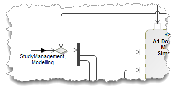
Figure 55 Example from AP242ed2 showing colour convention
Tip
The default symbol properties can be set for all new symbols using the “Set Selected Symbol style as default” button. The style can be applied to existing symbols using the “Apply default symbol style” button.
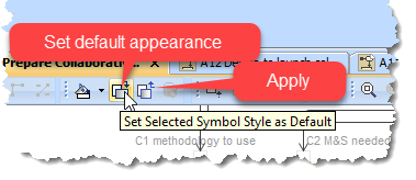
Figure 56 Setting and Applying default symbol styles.
Diagram layout conventions
The following are the IDEF0 syntax rules adapted to the use of SysML in the activity diagrams used in the application activity model:
- StructuredActivityNodes shall be organized diagonally from the upper left corner to the lower right, i.e., in a “staircase” configuration, unless an alternative configuration improves the readability or is a better use of space;
- The name of the StructuredActivityNode shall be centred in the box;
- Each StructuredActivityNode shall have a minimum of one input pin and one output pin;
- A StructuredActivityNode shall have zero or more control pins;
- A StructuredActivityNode shall have zero or more mechanism pins;
- Each pin on a diagram shall be the source or target of one ObjectFlow.;
- Where more than one ObjectFlow is needed at a pin, SysML Fork or SysML Merge nodes shall be used to convert between single and multiple ObjectFlows (see also Only one flow out of a pin and Only one flow into a pin);
- ObjectFlows shall be drawn as horizontal and vertical straight-line segments. Diagonal line segments shall not be used;
- Control feedbacks shall be shown as “up and over”;
- Input feedbacks shall be shown as “down and under”;
- Mechanism feedbacks shall be shown as “down and under”.
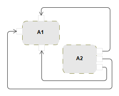
Figure 57 Object Flow Feedback arrows
Step by Step guide
Todo
the step-by-step for this section
The modelling steps are:
Video
Todo
Video does not show all the latest convensions:
- Names should be centred in boxes
- Stereotypes should be hidden
- Stereotype for “Resource” rather than “Mechanism”
The video shows creation of first activity, pins and flows.
Prepare the Top level Activity
Todo
the step-by-step for this section
Add element > Activity. Rename to “A-0 AP243”
Add diagram > activity diagram to the above activity
Add StructuredActivtyNode to diagram, covering most of the diagram area,
- rename “A-0 AP243”.
- Symbol Properties (Alt-Enter) UseFillColour - uncheck
Model the Activities, Pins and Information Flows
Todo
the step-by-step for this section
Add another StructuredActivtyNode inside the first
- rename “A0 Do M&S In Collaborative SE Context”
- change colour to RGB 231 231 231
Add element > input pin - to left edge of outer StructuredActivtyNode
rename to something e.g. “Input1”
double click to open properties,
- add AppliedStereotype of “Input” (part of STEPlib profile)
- change color and pen to white (so it disappears)
- uncheck Show Name
Add element > input pin - to left edge of inner StructuredActivtyNode
rename to something e.g. “Input1”
double click to open properties,
- add AppliedStereotype of “Input” (part of STEPlib profile)
- change color to white and pen to RGB 231 231 231
- uncheck Show Name
Tip
Stereotypes can be added to pins quickly afterwards by Drag and drop from tree to diagram
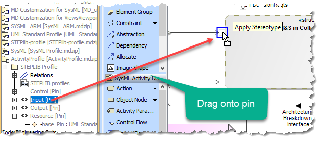
Figure 58 Drag and Drop Stereotype from tree to diagram
Add object flow from outer pin to inner pin (see the arrow disappear from inside the inner pin)
double click to open properties,
- Select Conveyed Information from menu on left
- Select suitable block from Conceptual_model
- Multi-selection option at bottom of window opens panel for multiple objects
see that the object flow arrow now has a solid black arrowhead in the centre
Mouse-R on object flow and select “Show Compartements”, select table “Information from X to Y” and then >> to move all to right. Now the CM objects are displayed
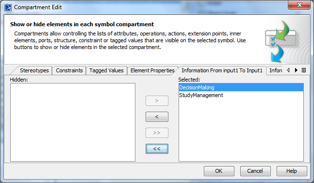
Figure 59 Edit Compartements to display conveyed information
Fork and merge
Tip
Drag and drop to split existing flows
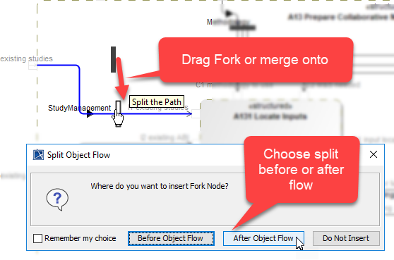
Figure 60 Drag and Drop Fork and Merge onto flow to split
The end
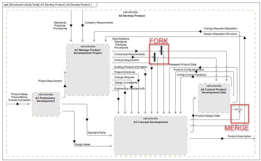
Figure 61 Completed diagram - Activity diagram for Activity “A0 – Develop Product” with fork and merge
Tunnelling
Tunnelling is used to simplify diagrams where an ICOR is used as-is by the recursive decomposition of that function. A ICOR is indicated to enter a tunnel by () on the pin of the function on the decomposition diagram, and the tunnelled ICOR and data flows hidden on all sub-function diagrams. If a sub-function uses the ICOR differently then it is shown on the outer node of the diagram and tunnel () added.
Important
The tunnel is a cosmetic feature of the diagram. All ICOR and object flows must be modelled recursively.
Tunnels on Input and Output pins are identified by adding the TunnelH stereotype.
Tunnels on Control and Mechanism pins are identified by adding the TunnelV stereotype.
A tunnel is displayed on the diagram by setting the symbol propert Show Stereotype to Shape Image.
This is visible in the containment tree and on the diagram.
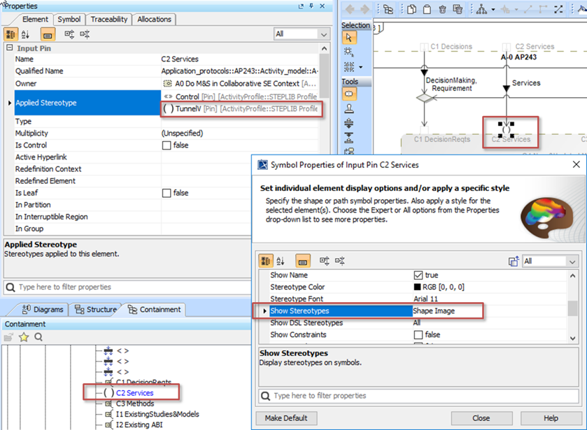
Figure 62 Control pin entering a tunnel
Section author: Judith Crockford (AP243)