STEPlib SysML: How To model Test Data

This page explains how use MagicDraw to model Test Data that can then be converted into sample implementation data or files for implementers. Test data can be for many purposes, the example described in this guide is for Test Data to illustrate a usage scenario.
The Test Data is modelled using SysML Instance Specifications.
Contents:
Prerequisites
This guide assumes that the following already exist:
- Domain Model (see How to model the Application Domain Model of STEPLIB)
- A model for the Test Data (see Create a new Application Protocol (AP) for instructions on creating models)
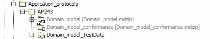
Figure 107 Prerequisite model setup for Test Data
Example Scenario
Scenario
This scenario is taken from the AP243 White Paper.
The example chosen presents the management of an ad-hoc study between two internal domain teams (using two different platforms) and an external supplier (using another platform). The use-case has the following steps:
Initiate - Prepare - Perform - Review - Initiate
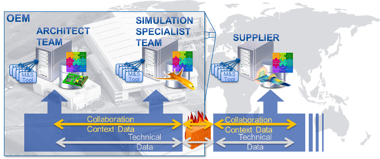
Figure 108 Example use-case for collaboration between internal teams and external supplier
Initiate design investigation study
During the concept phase of a new product family, an OEM Architect looks at the physical characteristics and performance simulation results for the current product and notices that:
Recent advances in materials technology have provided significant weight benefits on another product family which may be transferable to the new family.
- Architect [Team A], views simulation models from the structures experts [Team B] finding results for the new product that used properties for traditional materials, and also results for other family that used the new material. It was seen that new material simulation results were provided by the material specialist [Supplier])
The early simulations were conservative when compared to the physical testing resulting in an over engineered product. Therefore improvements in the simulation should be investigated.
- Architect [Team A], viewing simulation models from simulation experts [Team B], physical test results from [Team C not shown])
The OEM Architect decides launch a top level “weight reduction” study controlling two parallel studies, “materials technology” and “simulation improvement”, to investigate these ideas. Note: only the “materials technology” study will be elaborated in this illustrative example.
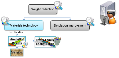
Figure 109 Initiation phase
Prepare
Using the architect’s software platform, the OEM Architect creates a “materials technology” study with the following:
Context: managed by the “Weight reduction” study
Justification: results from using this new material technology on other product families have shown significant improvements.
Concepts: New material technology
Objectives:
- Calculate the weight of the product with the goal of a 10% reduction from the baseline, this target justified by achievements seen in other families.
- Weight calculation results are to be within a 95% confidence level (i.e. accurate)
- Calculate the impact on the manufacturing cost (time and materials) within a 80% confidence level (i.e. rough estimate)
Constraints: Product outer shape remains fixed, though the internal structure can change
Inputs (as links to models on simulation expert’s platform):
- Geometry models for the outer shape
- Weight simulation results from baseline
- Manufacturing models from baseline
The OEM Architect then sets up a review with the OEM Simulation Experts in “Team B” with the result that the following high level tasks are identified for the study.
Tasks (ad-hoc because methods unknown):
- Generate new structural model that is suitable for new material
- Generate structural simulation results from structural model [delegated to Supplier]
- Compute weight with associated confidence level
- Verify weight and confidence are within specified limits
- Compute manufacturing time and materials with associated confidence level
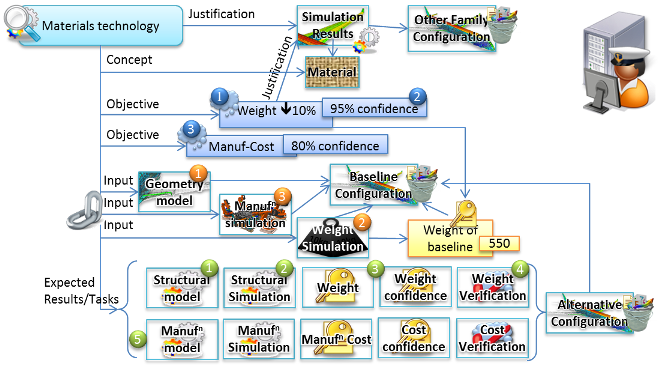
Figure 110 Study on conclusion of the preparation phase
Perform
The OEM Architect changes the study status to “launched”, this sends a notification to the OEM Simulation Experts, and their specialist’s software platform pulls the details from the architect’s software platform using MoSSEC web services
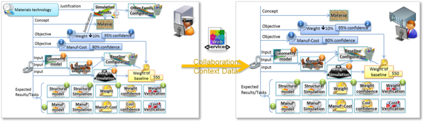
Figure 111 web services used to exchange study information
The OEM Simulation Experts review the request and, in discussion with the Supplier, adapts to include several intermediate steps needed to achieve the expected results. The image below shows the expected results (for the “weight” part of the study) with connections to the inputs, and elaborated with additional steps for; simplifying the structural model; creating a mesh; and modelling the uncertainty from the structural simulation. This adapt step could occur at any point and any number of times during the lifecycle of the study, for example, if an initial set of results have too low confidence an alternative simulation could be included in the study.
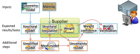
Figure 112 Elaboration by Team B of some of the expected results for the example
The OEM Simulation Experts start work generating the expected results. Where the inputs are provided as links, the specialist’s software platform downloads the technical data from the linked platform. When each result is available the specialist’s software platform updates the architect’s software platform with links to the results and an updated status, as shown in the adjacent image where change in status is indicated by green border.
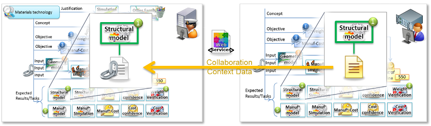
Figure 113 Web services used to update status and provide link to results data
When all the inputs are available that are needed for the step that has been delegated to the Supplier, a notification is sent to the Supplier. At the same time the associated inputs are posted to a collaboration hub that is outside both the OEM’s and Supplier’s firewalls though controlled by the OEM. For this example the collaboration data is posted using MoSSEC web services, and the technical data is posted using file exchange e.g. in STEP AP242 Part28 format. Unlike the exchange between the OEM teams where links to the technical data were used, supplier does not have permission to follow the links through the firewall so the technical data must also be exchanged. Both the collaboration data and the technical data can include associated information rights and security classifications.
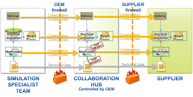
Figure 114 Exchange with supplier through firewalls via collaboration hub
Exchange with supplier through firewalls via collaboration hub In a similar way, the supplier generates the expected results and post updates of the collaboration data (e.g. status updates and weight KPI values) and technical data (e.g. results files) and any other pertinent information (e.g. assumptions made during simulation) back to the collaboration hub. These are retrieved by the Simulation Specialist platform and exchanged with the architect’s platform
When all the results data and KPI have been computed, the simulation specialist assesses if the objectives have been met, and updates the verification status accordingly. At the conclusion of the perform phase the data is sent from the specialist’s platform to the architect’s platform with the result
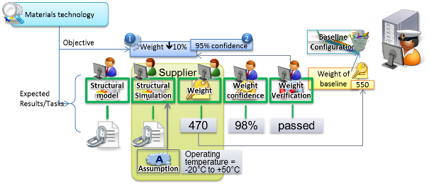
Figure 115 Updated collaboration data and links to results data in Architects platform
Review
At any point in the lifecycle of the study the OEM Architect can review the progress and any available results. In this illustration it is assumed that all the results have been published and the OEM reviews the following:
- Weight value, sees that it is significantly improved from the baseline and wants to review how this was achieved
- Notices that the weight is computed from the Structural Simulation results, so looks to see what simulation method was used to generate these results. Next chooses to look at the technical results in detail so clicks on the link to the results in the specialist’s software platform. This opens a window in the architect’s software platform with a viewer for the results. Checks that these are of the expected quality.
- Notices that the supplier has added an assumption about the operating temperature range, opens the details of that assumption, decides that it is valid, and adds an approval to the assumption (perhaps also adding a justification to explain that is valid because this baseline is within this range)
- Notices that the verification of the objectives has been set to “passed”, so signs off the approval for that verification.
As the results from the other parts of the study become available the OEM architect discovers that although the weight is improved by using the new material technology, the manufacturing cost has significantly increased. By looking at the costs in more detail it becomes apparent that one part of the structure has more impact on these costs than the rest.
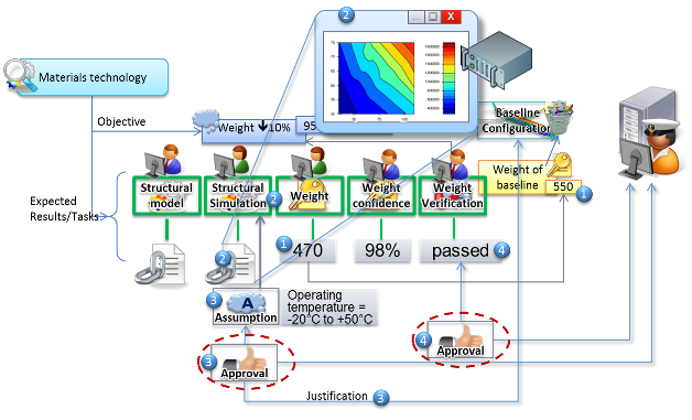
Figure 116 Review technical results and assumptions; add approvals
Initiate follow-up study
The OEM Architect decides to launch a follow-up study where the part of the structure that had highest impact on the manufacturing cost uses conventional materials and the rest of the structure uses the new material. A review of the traceability from the different studies shows that the results from some of the intermediate steps can be reused (e.g. the simplified model and the mesh model) and other steps can use the same models to generate results from the updated inputs. Therefore a new study is launched that includes results from the previous studies and adds new tasks to rerun the results computation for the updated inputs.
Step by Step guide
The video shows the steps in this process.
Create a new package and Object Diagram
The packages are used to structure the implementation technology specific sample data. For example for the file exchange XML, the <DataContainer>s reflect the first level of packages.
Having created suitable packages, add an Object Diagram to the packages. The Object Diagram is available from General list for the Expert filter.
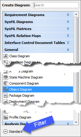
Figure 117 Object Diagram selection
Add new Instance Specifications
The Test data is modelled using SysML Instance Specifications.
New Instance Specifications are created by dragging the Instance from the menu onto the diagram. This will open a Select Classifier dialog as shown below. Turn the filter off to be able to see the Domain Model entities. This will also show all other entities including the Core Model, so hover the mouse over the block icon to show the namespace tool tip to tell which is which. The type-in box at the top can be used to filter the list.
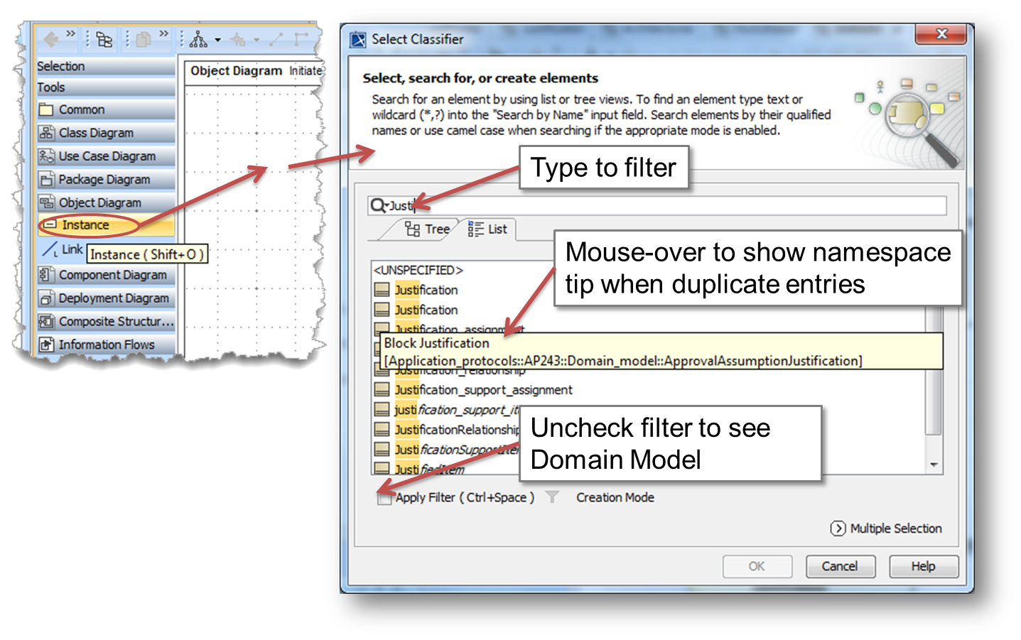
Figure 118 Object Diagram selection
Edit the name, either in the diagram or in the tree.
The default display is to show all the public slots with values. This will include elements from the mapping that were provided with default values, typically for classifications. These should be hidden using the Edit Compartments
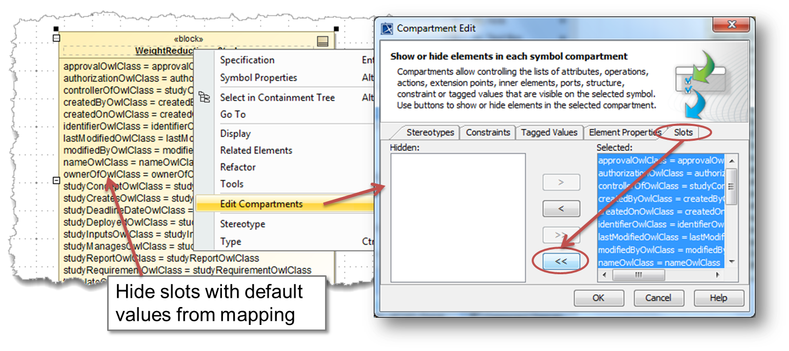
Figure 119 Hide Slots with default values from mapping.
Setting Slot values
There are two methods for setting values for the slots:
Using Links in the diagram
Links are created between entities on the diagram. These can be new Instance Specifications (as described above) or existing Instance Specifications can be dragged from the tree onto the diagram.
The process for creating links is as follows:
Create a new link either by hovering over the entity and selecting the link icon, or by selecting the Link from the controls
Select the entity to link to.
If there are properties linking the two types in the Domain Model, it will popup a Select Association dialog
- Only valid links should be created, therefore it the Select Association dialog does not appear the link should be deleted
- The Select Association dialog will list the properties in both directions.
- Select the association(s) and click OK (multiple associations can be selected)
A Create Slots will appear for each checked association in the previous step. Leave it at the default and press OK
The diagram will now show the link and the newly set slots.
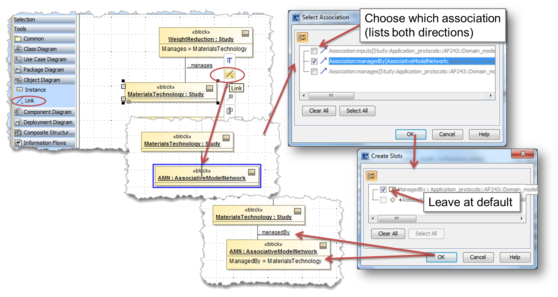
Figure 120 Using Links in the diagram to set Slot values.
Using Specification dialog
It is possible to create and edit the Slot values using the Specification dialog. This is accessed using double-click or Enter from diagrams or the tree.
The following are of interest:
- The Slots are shown by selecting in the left tree
- The Slots are listed alphabetically and grouping by their owning block can be toggled on/off
- Slots with a value are shown in bold with the circular slot icon
- Slots with no value show the rectangular property icon with a letter showing the type of property (C=Constraint, P=Part, R=Reference, V=Value)
- The list shows both the public and private properties. Only the public should be set and these can be identified by the UpperCamelCase naming convention
- Set a slot value by selecting and then clicking on Create Value
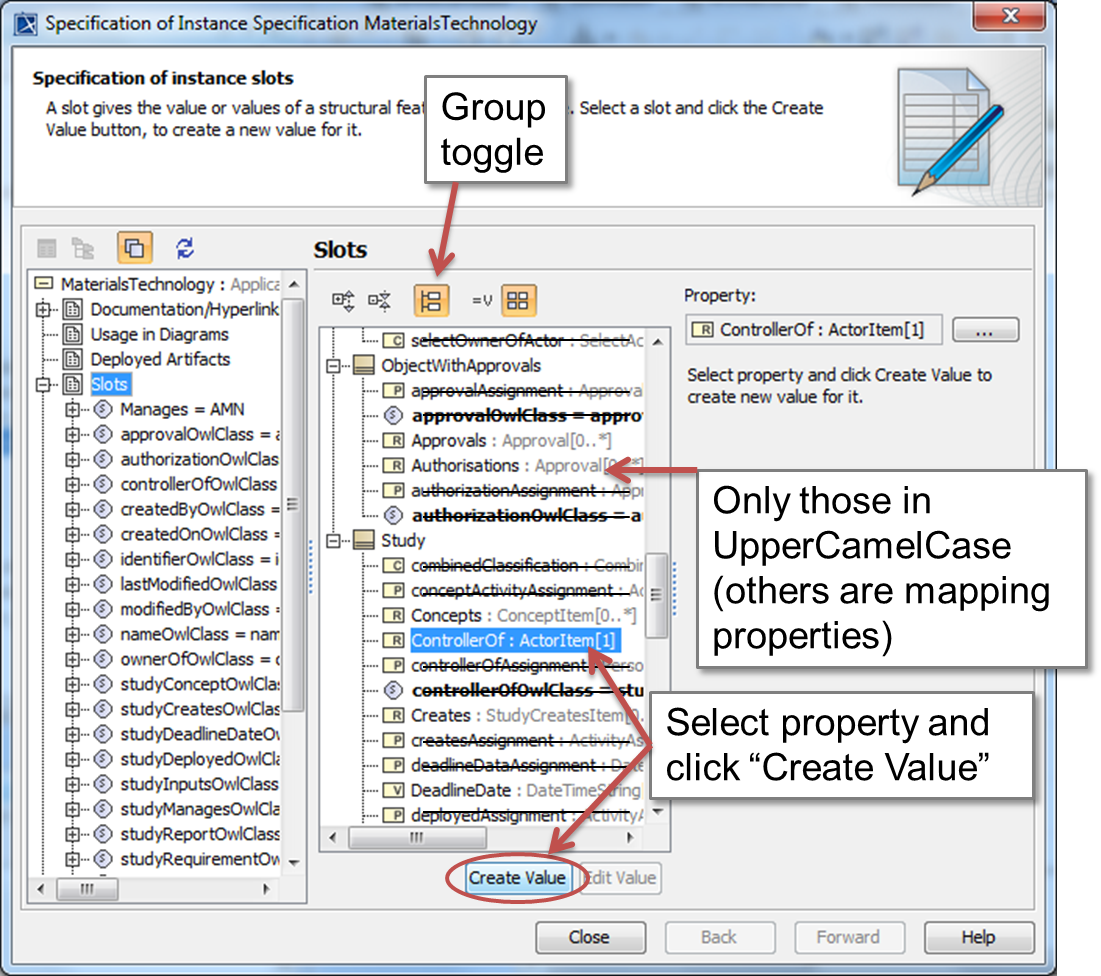
Figure 121 Property Dialog for editing Slots.
Depending on the type of property being edited different options are presented (see figure below):
- Part and Reference Properties - a Select Instance Specification dialog is presented to select the other entity
- Value Properties of Enumerations - the enumeration is displayed as a drop-down list on the right of the Specification dialog
- Other Value Properties - a type-in panel is displayed on the right of the Specification dialog
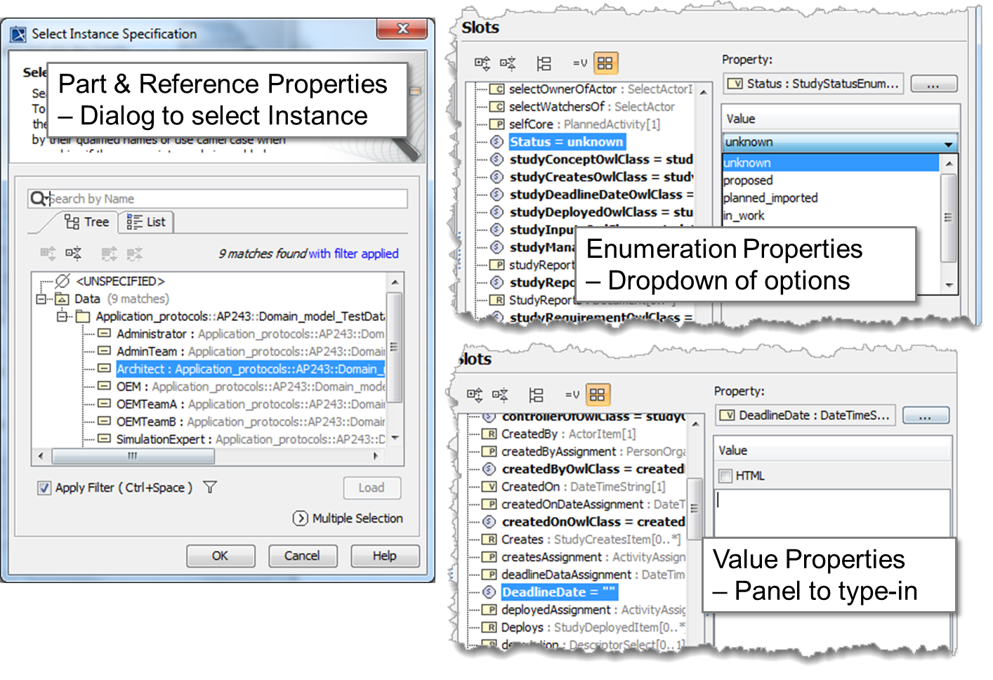
Figure 122 Different editors for Reference/Part, Enumeration and Value properties.