STEP extended architecture high-level description

Note
Content taken from N3999 (12 Sept 2019)
Contents:
Fundamental concepts of the STEP extended architecture
Contents:
This page describes the fundamental concepts of the STEP architecture extensions that are agreed upon for use in ISO 10303-243 first edition and ISO 10303-239 third edition. Some background is given on the STEP architecture and its evolution, to provide context for the proposed architecture changes. The high-level requirements that led to the development of the STEP architecture extensions described in this document are shown below. The requirements themselves are in a living document maintained by ISO TC 184/SC 4/WG 12. Snapshots of the requirements will be published with the standing documents that implement those requirements.
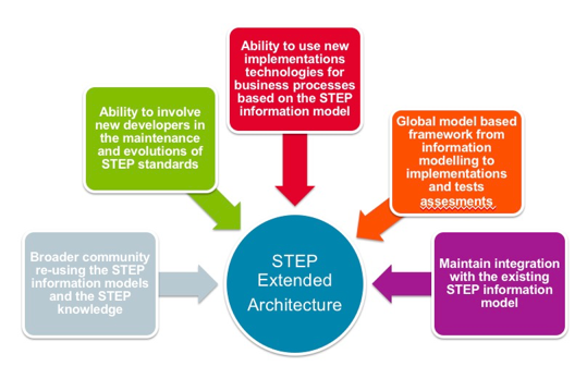
Figure 1 Primary requirements for the STEP extended architecture
STEP three-layer architecture
The STEP architecture is adapted from the ANSI/SPARC three-layer architecture. In STEP, the three layers are the business layer, the information requirements layer and the implementation layer, as shown below. These layers are characterized by different models with different purposes. While there have been architectural changes to STEP over the years, the underlying three-level architecture still applies.
The business layer consists of an application activity model (AAM) that describes the business processes the information model supports. The AAM is the result of the first stage of AP development, analysis of the use cases and business processes that drive identification and scope of the initial information requirements of the AP.
The information requirements layer consists of two distinct types of data specifications: integrated resources and application protocols. Three classes of information models are specified within these two types of specifications.
The first class of information model is the integrated resources, a collection of standardized EXPRESS schemas specified in ISO 10303-40- through100-series parts. Each integrated resource schema is a representation of a specific subject area within the domain of product data. The integrated resources are abstract conceptual structures of information that are generic with respect to various types of products and different stages of the product life cycle. These models provide the foundation for STEP integration.
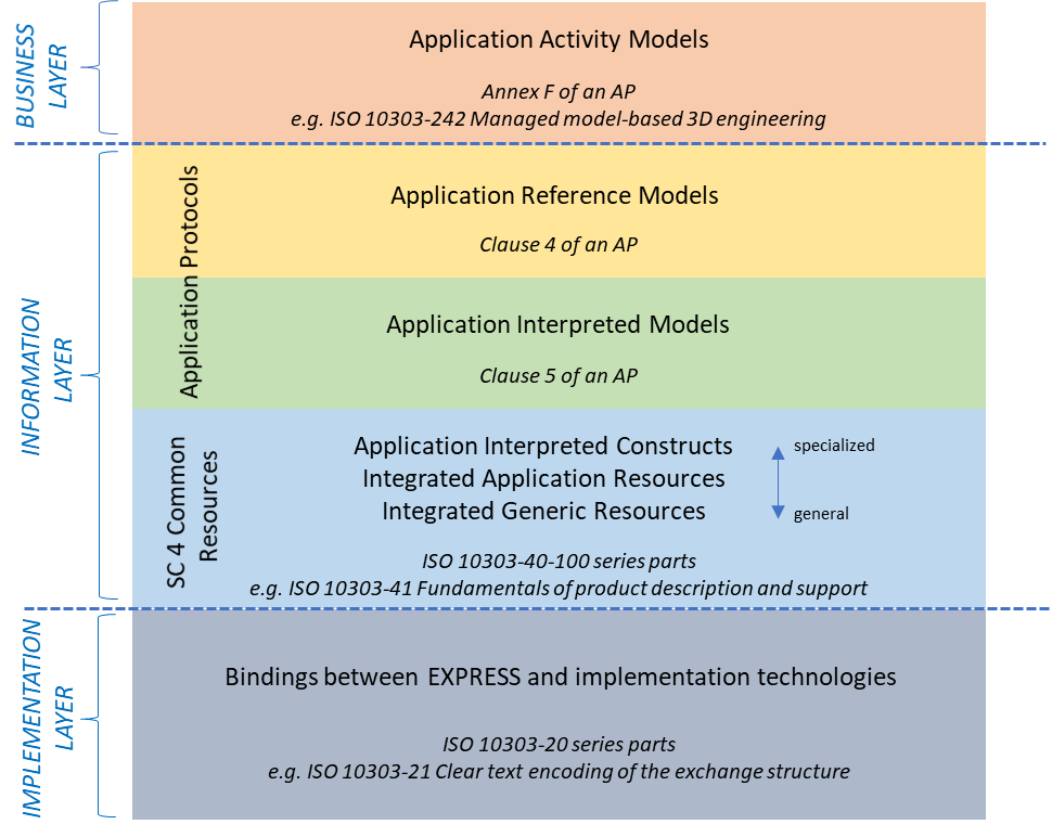
Figure 2 Models in the STEP three-layer architecture
The second and third classes of information models are traditionally contained in ISO 10303-200-series parts called application protocols (APs). APs are the series of parts that are intended to be implemented in software systems. The AP information models are the application reference model (ARM) and the application interpreted model (AIM).
An ARM captures the information requirements for an application context which has a scope bounded by a specific set of product types and product life cycle stages. An application reference model (ARM) specifies the information requirements in domain terminology. This model, as originally intended, is used by domain experts to understand the extent and relationships between information represented by the AP. ARMs are currently modelled in EXPRESS. More information about application reference models is provided in 4.3.
The AIM is based on SC4 common resource models that are the basis for consistent implementation of the standard, but still define the information requirements independent from implementation concerns. More information about application interpreted models is provided in 4.2.
The implementation layer consists of language bindings that provide the means for developing implementations of the information requirements and the resulting implementation forms. The models in the information requirements layer can be implemented using different technologies for different purposes.
The STEP three-layer architecture separates the concerns of different stakeholders (executives, domain experts, software developers) so that the resulting AP is easier to understand and validate, interoperability is facilitated, and requirements specifications are independent from changes to business practices and from changing implementation technologies.
Information layer model relationships
The three types of models in the information layer of the STEP architecture are related through the process called interpretation. Interpretation is the selection and specialization of constructs from the integrated resources that satisfy the information requirements of the ARM. In this process, an AIM short form is developed and a mapping specification documents the relationship between the ARM and AIM constructs. The interpretation process and the development of the AIM is described in the Guidelines for application interpreted model development. Mapping specifications are described in Guidelines for the development of mapping specifications.
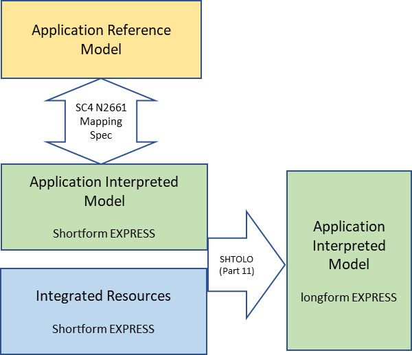
Figure 3 Information layer model relationship
The AIM EXPRESS schema references applicable constructs from the integrated resources as baseline conceptual elements. An AIM may augment the baseline constructs with additional constraints and relationships, which are specified by new subtype entities and local rules, refined data types, global rules, and specialized textual definitions.
An AIM is documented in three forms within an AP: an EXPRESS short listing containing inter-schema references and constructs unique to the specific subject area and a completely independent EXPRESS longform schema where references to external schema are resolved according to the interfacing rules of EXPRESS. This is frequently referred to as short-to-longform generation, or SHTOLO after the NIST reference implementation of this algorithm.
The longform AIM is the schema used by applications to support data exchanges as defined by implementation layer bindings such as Part 28, Part 26, and Part 21.
STEP modular architecture
In 1999, interoperability concerns led to the development of the STEP modular architecture. The development of the ISO 10303 modular architecture was driven by the following requirements:
- to reduce the high cost of developing an application protocol;
- to ensure the ability to implement a combination of subsets of multiple APs or to extend existing APs to meet a business need;
- to ensure the ability to reuse application software developed to support one AP in the development of an implementation of another AP with the same, or similar, requirements;
- to avoid the duplication and repeated documentation of the same requirements in different application protocols leading to potentially different solutions for the same requirements; and
- to ensure the ability to reuse data generated by an implementation of one or more APs by an implementation of one or more different APs.
Application protocols had been monolithic, stand-alone standards, each containing all the information needed to support use and implementation of the standard by industry. Modularization separated capabilities or functions of the AP into separate standards, called application modules (AMs) that could be re-used. AMs providing constituent capabilities for an AP were combined into a top-level module, a separate standard in the 10303-400 series, referenced by the AP document, as shown below. The modular architecture was enabled through an XML-based software development environment called STEPMod.
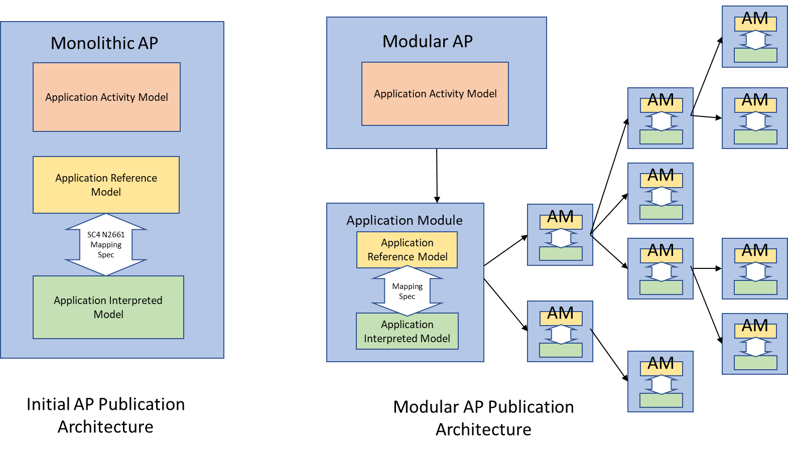
Figure 4 Changing document architecture for STEP
This change modified the STEP architecture information layer as shown below.
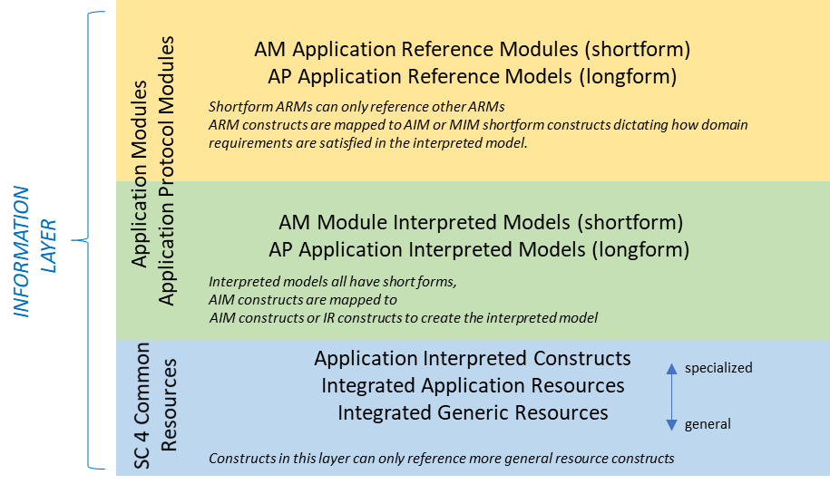
Figure 5 Information layer in the STEP modular architecture
In the modular architecture, application modules specify shortform EXPRESS ARMs. The top-level, or AP application module ARM is a graph of application module (AM) ARMs that reference other application module ARMs. These are considered shortform EXPRESS models because the model is only complete when the interfacing rules of EXPRESS are followed to resolve all the references into a longform schema (also called an expanded listing).
Time has revealed shortcomings in the STEP modular architecture. The primary goal of modularization (reusability) came into conflict with the goals of the ARM (expression of requirements in terms domain experts understood). The AP-specific ARM that included the complete set of requirements was replaced with a collection of modular ARMs broken across many documents. The collection of modular ARMs is not useful to domain experts in reviewing the contents of an AP.
Rationale for extending the modular architecture
The STEP extended architecture is based on the modular architecture. Several issues were identified as the basis for the need of these extensions.
- The introduction of an XML schema in ISO 10303-3001, in ISO 10303-242(2014) was an evolutionary step to define a normative XML schema for a STEP AP. Although there was an XML binding for STEP, the binding did not satisfy the industry requirement to provide a model suited for service implementations. The new business object model, ISO 10303-3001, introduced two issues: 1) many business objects were not properly mapped to the information requirement models in the AP; and 2) future XML schemas are now constrained to be backwards compatible with ISO 10303-3001.
- Development of EXPRESS language schema is limited by the small number of EXPRESS tools.
- Data exchange software technologies are anticipated to continue to evolve. The extensions proposed for the STEP architecture are to support alternative implementation forms.
STEP extended architecture
In the STEP extended architecture, a new model type, the application data planning model (ADPM), is added to the STEP architecture business layer, and two new model types, the application domain model (ADM) and the core model (CM), are added to the STEP architecture information layer. The ADPM defines the data planning objects that are referenced as information flows between the activities in the AAM The ADM defines business objects for a specific industrial application and particular segments of the product lifecycle. These are referenced by the ADPM data planning objects. The CM defines the complete and comprehensive information model, shared by all ISO STEP Application Protocols, representing the product data through its entire life cycle . The application domain model and the core model are specified in the Object Management Group’s systems modelling language (SysML). In the extended architecture, the AAM and ADPM are specified in SysML and the ARM is translated to SysML. The application domain model is mapped to the core model which is in turn mapped to the ARM in SysML, all using SysML parametric diagrams. The ADPM data planning objects reference the application domain model business objects to define how the domain model covers the scope of the application activity model
The application activity model, the application data planning model, the application domain model, the application reference model and the application interpreted model are specific to each application protocol. Some elements of these models can be shared by multiple APs. The core model is common to all APs.
In addition to the SysML models described above, Reference Data Libraries are included to enable the models of the information layer to be extended. The diagram below presents the STEP modular architecture components alongside the extended architecture components.
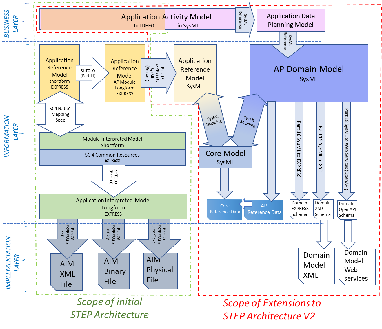
Figure 6 Relationship of STEP extended architecture existing STEP components
The mappings from the ADM to the CM and the CM to the ARM are realized using SysML parametric diagrams. The mappings from the ARM to the AIM are realized with STEP mapping tables.
The description of the extended architecture models and mappings are described in clause 5, the extended architecture development environment and software tools are described in clause 6.
Reference data in the STEP extended architecture
Reference Data is the mechanism for extending the semantics of an information model. It is used with the Core Model for common reference data; in Application Protocols for domain specific reference data; and within projects or organizations extending for specialized exchange requirements or specific business context reference data. This is illustrated below.
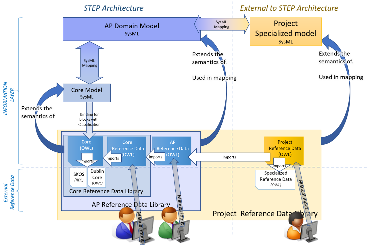
Figure 7 Reference Data architecture
The Core OWL is generated from the classifiable blocks of the Core Model and imports standard libraries such as SKOS and Dublin Core. The Core Reference Data imports the Core OWL and is manually edited with additional content. Together these form the Core Reference Data Library which extends the semantics of the Core Model.
Content for the AP Reference Data imports the Core Reference Data and is manually editied with additional content. The AP Reference Data Library extends the semantics of the AP Domain Model.
The architecture for an AP can then be repeated for the project and organization reference data libraries external to the STEP architecture.
Implementation in the extended architecture
Applying a language binding to an information model of interest results in an implementation schema. Implementations of different models satisfy different sets of industry requirements. The decision to define a normative implementation model, or service, for a specific model is under the responsibility of the standardization committee ISO TC 184/SC 4.
The STEP modular architecture defines the AIM as the AP-specific, normative, implementation model for implementations through bindings to the various implementation technologies, e.g., 10303-21, 10303-26 or 10303-28. This capability is preserved in the STEP extended architecture.
In addition to the above, the STEP extended architecture permits implementation of the new information model, the application domain model. Implementation may be through a normative XSD schema or an equivalent EXPRESS schema, both of which are derived from the SysML domain model.
Changes to STEP components in the extended architecture
Contents:
Application protocols in the extended architecture
An AP specifies an information model, suitable not only for neutral file exchange, but also as a basis for implementing and sharing product databases and archiving, and for services based implementations, for an application. For a monolithic AP, the information model is specified as an integral part of the AP document. For a modular AP, the information model is specified by reference to the AP module. For an extended architecture AP, the information model is specified by reference to the AP domain model and the AP module depending on the implementation use cases.
An AP consists of the following major elements, some of which may be documented in referenced specifications:
- an application activity model describing the business activities the information model supports;
- an optional application data planning model describing the types of data that flow between the business activities.
- an optional application domain model specifying the information model for normative implementation models of the standard;
- an application reference model specifying the information requirements for the application protocol;
- an application interpreted model that is the usual basis for STEP implementations.
- An optional reference data library
NOTE AP242 ed1 includes a business object model (BO Model). This BO Model will be deprecated with the STEP extended architecture and replaced by an application domain model.
Application activity model
The application activity model is a model that depicts the industry activities and information flows to be supported by the Application protocol. An application activity is a group of one or more activities creating or using product data. The AAM is part of the AP’s functional analysis. The AAM has the following functions in the architecture:
- The application activity model is intended to communicate and define the in-scope and out-of-scope activities of the application protocol to the external world. Activities and data flows that are out of scope are marked with an asterisk.
- The application activity model is built to the appropriate granularity to provide the information requirements for the application domain model and the application reference model. Any activity can be decomposed into a set of sub-activities.
- The application activity model information flows become the basis for the business objects in the domain model; all information flows relevant to the scope of the application protocol shall be represented and defined in the application data planning model, the name of the in-scope information flows will be defined in the application data planning model.
- The application activity model is informative. It does not represent a specific organization process. It is not a normative process to be implemented by organizations.
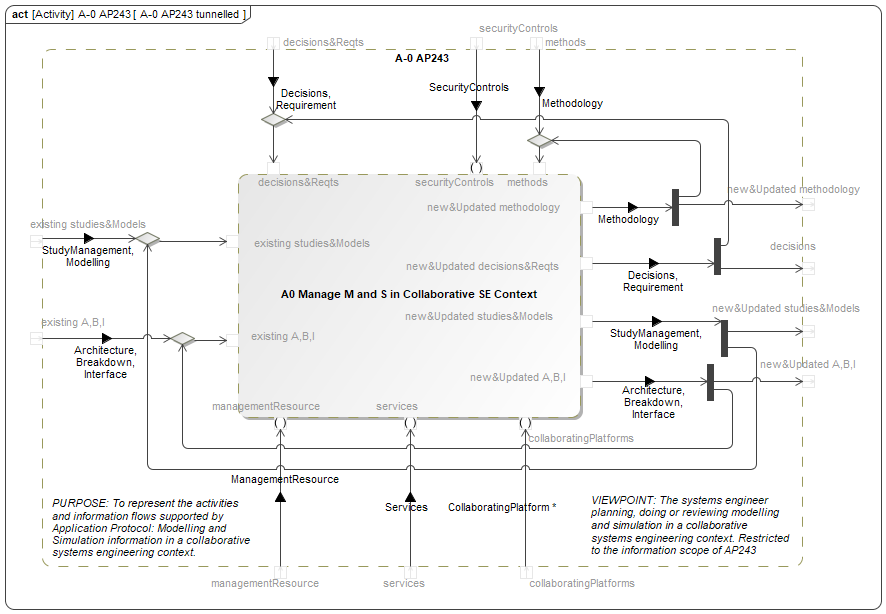
Figure 8 Depiction of an application activity model in SysML
The application activity model may be partitioned into diagrams to share or reuse activities between activity diagrams. A shared activity definition shall be completely defined and managed in one single application activity model. This activity can be reused in multiple activity diagrams.
An application activity model is based on a specific viewpoint. An AP may include multiple viewpoints and therefore multiple activity diagrams. The architecture shall be able to support establishing relationships between activities in the multiple activity diagrams included in the AP.
The application activity model is defined by a set of SysML diagrams equivalent to the IDEF0 representations.
Application data planning model
The application data planning model of an Application Protocol provides the high-level concepts, structure and relationships of the information model that the AP supports. The public for the model is the external business end users and enterprise architects.
The items of the data planning model are called data planning objects.
The business goal of the data planning model is to document the application activity model by providing the following functions:
- Provide the external business end users with an understandable definition of the scope and use of the AP;
- Provide the standard implementers an entry point in the ISO 10303 methodology and technology by providing explicit links for navigating to other parts of the standard;
- Provide a more accessible mechanism for the enterprise architects to understand the conformity options of an AP;
The business goal of the data planning model for the SC4 community is to:
- Provide traceability back to the original user requirements;
- Provide a consistent set of data planning objects by reusing them across data planning models for various APs.
The roles of the data planning model for STEP development are:
- Provide requirements to the STEP developers for defining name and design rules for implementation models;
- Provide requirement for partitioning of the information structure;
The details on STEP data planning in SysML are illustrated below.
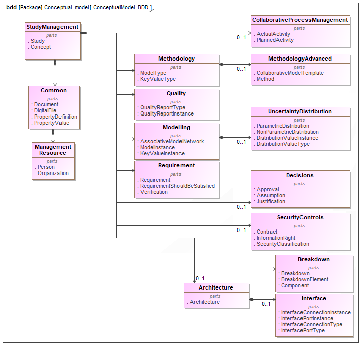
Figure 9 Depiction of Application data planning model in SysML
Application domain model of an AP
The application domain model describes the information requirements and constraints of a specific application context in a normative schema definition. The application domain model is a specific view of selections of the STEP integrated model constrained by the application protocol requirements.
The domain model is represented as a SysML model containing block definition diagrams and parametric diagrams. The models are stored independent of the authoring application as XMI representation. Part 15 specifies a mapping from the XMI representation to an XML Schema Definition (XSD). Part 16 specifies a mapping from the XMI representation an EXPRESS schema. ISO 10303-18 specifies a mapping from the XMI representation to a services definition using an OpenAPI schema. The resulting XSD, domain EXPRESS schema and OpenAPI schema will have the domain model as a shared definitional basis and can be considered semantically equivalent. A key consideration during this transformation is in how rules are handled. For the domain model, the EXPRESS rules have been recast to the Object Constraint Language.
The items in the application domain model are called the domain objects. Domain objects are defined by their attributes and their relationships with other domain objects. The domain objects are created in SysML.
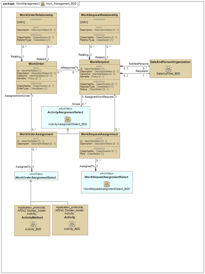
Figure 10 SysML block definition diagram representing the work management domain objects
The XSD schemas and OpenAPI schemas are derived from the domain model by applying the implementation bindings on the domain model. The bindings are realized with XSLT stylesheets stored in AntImp (see 6.3) which transform the SysML model into the Schemas.
The optional AP Reference Data library imports the Core Reference Data library which provides the sub class references. It is derived from the Domain model and mapping to the Core model, and imports Domain Reference data.
ARM in SysML
With the staged integration of the extended architecture SysML models, an artefact, called the ARM in SysML, has been added to enable the mapping from the core models to the ARM. The ARM in SysML is an interface between the modular architecture and the extended architecture.
The ARM in SysML is generated from the EXPRESS ARM longform schema in accordance with ISO 10303-17, using software called REEPER (see below). The ARM in SysML longform schema is a semantic equivalent to the ARM longform schema, with the exception that the EXPRESS ARM contains rules that are not preserved in the generation of the SysML ARM.
The ARM in SysML is the baseline model through which the core model is integrated with the modular architecture. The core objects, are mapped to ARM application objects [AO]. The purpose of the mapping is to ensure that each core object can be traced to the AOs in the Application module [AM]. Each AM has a mapping specification of the path from the AO to MIM entities and STEP integrated resource entities. The application domain model objects are mapped to the core model objects and the two mappings ensure that each domain object can be traced to the AOs in the AM.
Through the AP242 / AP39 harmonization activity, the Core Model is a re-statement of the information requirements compliant with the 442 ARM and the 439 ARM . The Core Model is, therefore, not fully aligned with the combined 442 and 439 ARM longform; however, the Core Model SysML is completely mapped to the ARM SysML using Parametric diagrams. The integration of the Core Model and the ARM SysML was enforced by adapting both the Core and ARM models to enable all mappings to be completed.
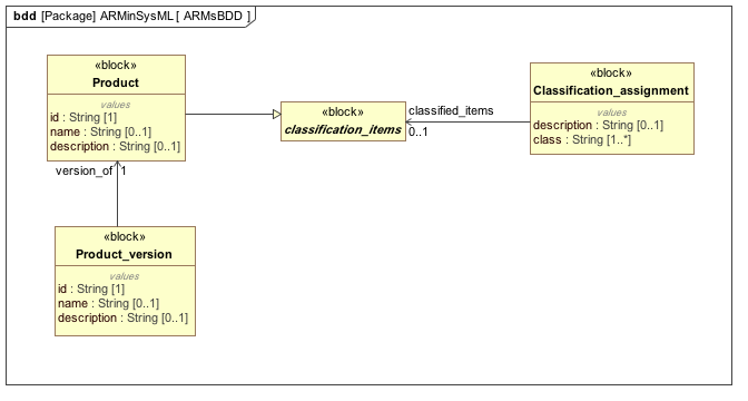
Figure 11 Application object from the ARM in SysML block definition diagram
The domain model/core model/ARM mapping
This mapping specification defines how each domain model element maps to one or more core model elements that are in turn mapped to one or more ARM elements.
The SysML core objects provide a mapping target from each domain object, including its attributes and assertions. Because each core object has a mapping to the application object in the SysML ARM that has a mapping specification to entities and assertions in the application/module interpreted model schema, there is a complete path from the domain object to the entities and assertions in the AIM. This path ensures that each domain object is using semantics and relationships that are identical to the ARM longform schema and ensures that the AIM entities and IR entities provide the basis for the domain model.
The mappings from the domain model to the core model and from the core model to the SysML ARM model are realized by a set of SysML parametric diagrams as shown below.
Figure 12 Core model to ARM mapping in SysML parametric diagram
Core model in the extended architecture
The role of the Core model is to specify a complete and comprehensive information model shared by all ISO STEP Application Domain Models. The Core model is intended to represent the product data through its entire life cycle.
The Core Information model is decomposed or partitioned into a set of Core Technical Capabilities (CTC). A CTC is a set of objects and relationships that can be reused in, or customised by, any Application domain model. Each CTC is represented as a SysML model containing block definition diagrams and parametric diagrams using the same methodology as the Application domain model of an AP. The models are stored independent of the authoring application as XMI representation.
A CTC is constrained and defined as follows:
- A CTC shall be a consistent group of core objects;
- One core object is declared in one and only one CTC, the CTCs do not overlap;
- A CTC is formalized as a set of core objects and relations, which may include references to core objects in other CTCs. Objects and relations are fully defined, including all attributes and constraints, and fully documented.
- Core objects and relations may be used to derive an implementation form;
- A CTC shall provide interfaces and auxiliary information.
- A CTC shall group functionally related elements to reduce the links between capabilities.
- A CTC shall be meaningful to the user community, i.e. associated to a generic information sub-domain.
- A CTC can be decomposed into domains and subdomains using in SysML Packages, for example, multidisciplinary simulation decomposed into thermal analysis, finite element analysis; or Product and Manufacturing Information [PMI] decomposed into Generate and Test [G&T], Dimension and Tolerance [D&T], Weld, etc.
The Core Reference Data is derived from the Core model and is manually updated with additional content.
Changes to other STEP components
Implementation forms
The STEP extended architecture requires new bindings to derive the implementation forms from the AP domain model. The implementation forms for the extended architecture are listed in Table 1 below.
Table 1- Extended architecture implementation methods
| Information Model | Modelling Language |
|
Schema Language for implementation | Data Format for implementation |
|---|---|---|---|---|
| Application domain model | SysML | domain model XSD | XML Schema | XML |
| domain model EXPRESS | P28 XSD | XML | ||
| Domain model OpenAPI | JSON schema | JSON or XML | ||
| ARM | EXPRESS | none | ||
| AIM | EXPRESS | AIM Long Form | P11 EXPRESS | P21ed3 |
| P28 XSD | P28 | |||
| P26 HDF | P26 | |||
| BO Model | EXPRESS | BO Model XSD | P28 XSD | XML |
NOTE AP242 ed1 includes a business object model (BO model). This BO model is being deprecated with the STEP extended architecture and replaced by an application domain model.
Domain model XSD
A domain model binding to XML implementation is proposed for the data exchange with XML documents based on the domain model. The binding is an XMI to XSD transformation based on XSL. The XSL definition for the Domain to XSD binding is defined in ISO 10303-15 (to be published).
NOTE Data quality checks can be done at the syntactic level by checking the datasets against the XSD schemas, and semantic checks can be realized by XML checkers.
OpenAPI
A domain model binding to OpenAPI JSON schema is proposed for the data exchange with web services based on the domain model. The binding is an XMI to OpenAPI transformation based on XSL. The XSL definition for the Domain to OpenAPI is defined in ISO 10303-18 (to be published).
NOTE Data quality checks can be done at the syntactic level by mock servers checking the web service content against the OpenAPI schemas. Semantic checks can be realized by virtual servers.
STEPlib
Contents:
STEPlib is a management system that contains the complementary data and tools needed for the development and publication of the STEP extended architecture. The tools and data are used to:
- manage the SysML models during the development of the models;
- prepare content to be fed into STEPmod for publication: AntPub;
- implement the SysML to XSD binding: AntImp;
- transform the ARM EXPRESS model into the ARM in SysML model to build the SysML mappings from SysML models to EXPRESS models: Reeper;
- check the quality of the SysML source content: CheckXMI.
STEPlib does not deprecate use of STEPmod. As before, the EXPRESS-based modular STEP development is managed by STEPmod and the WG12 Bugzilla server.
STEPlib is designed for managing the development of the specific components of the extended architecture models and producing the associated documentation subsets which will be assembled in STEPmod for ISO publication.
SysML environment
A SysML editor implementing SysML 1.4 and OCL 2.4 shall be used to develop the SysML models and diagrams in STEPlib. The STEP extended architecture does not specify the use of a specific SysML editor. Tests have been made with commercial and open source editors to validate the capability of the tools to support the specifications. SC 4 N3401, STEP extended architecture detailed STEPlib specifications, describes recommendations for SysML use.
SysML to canonical XMI
The normative SysML representation for the publication of the standard is the canonical XMI as defined in Annex B of the XMI specification. The developers shall export their SysML models in canonical XMI to feed the publication process of STEPlib. The canonical XMI of SysML models have been generated using the script to_cxmi.rb.
Canonical XMI to SysML
To modify the SysML model of the standard, the canonical XMI is the reference model and it needs to be transformed into an editable version to be processed by the SysML editors. The translation component canonical XMI into SysML is to_md.rb.
Model repository
A model repository is needed to share the SysML models during the course of the development. The target for the STEP extended architecture is to use the ISO collaboration source control GIT environment bitbucket. Development teams can take advantage of the distributed nature of the GIT framework and a complementary source control environment synchronized with the upstream ISO server.
For the AP242 ed2, AP243 ed1 and AP239 ed3 development, the GIT upstream server is located at git2.boost-lab.net.
AntPub
AntPub is a set of tools, whose main components are XSLT style sheets, which extract the list of all entities of a model and their descriptions from the SysML XMI. For the ISO part of the model it produces:
- 10303-2xx - Clause 4;
- 10303-2xx - Annex F (AAM)
- 10303-44xx - Clause 4;
- 10303-44xx - Clause 5 with the list of all mappings;
- 10303-44xx - Annex C with the list of all block definition diagrams;
- 10303-44xx - Change Annex from previous edition;
- List of XMI ids for the entities and their attributes to feed the image maps navigation.
The resulting HTML documents are stored in STEPmod to build the ISO document using STEPmod build scripts.
AntPub can be downloaded at http://git2.boost-lab.net/harmonization/Harmonization-STEP-updated-architecture/tree/CTC-harmonization_rebased/STEPlib/utils/AntPub.
AntImp
AntImp is a set of tools, whose main components are:
- XSLT style sheets DomainModel_xmi_to_xsd.xsl, which reads a SysML model in XMI and:
- Transforms it into an XSD schema following the XSD definition rules defined by ISO 10303-15 (to be published);
- Compares the XSD schema with the one from the previous version.
- XSLT style sheets DomainModel_xmi_to_json.xsl, which reads a SysML model in XMI and:
- Transforms it into an OpenAPI JSON schema following the definition rules defined by ISO 10303-18 (to be published);
- Compares the XSD schema with the one from the previous version
AntImp can be downloaded at http://git2.boost-lab.net/harmonization/Harmonization-STEP-updated-architecture/tree/CTC-harmonization_rebased/STEPlib/utils/AntImp.
Reeper
Reeper transforms an EXPRESS schema into an XMI model. Reeper is used to produce the ARM in SysML to define the Core Model to ARM mapping.
Reeper can also be used to transform any EXPRESS model into a SysML model suitable to derive a domain model in the extended architecture. Reeper is used to update the ARMinSysML models.
Reeper can be downloaded at https://sourceforge.net/projects/reeper
CheckXMI
CheckXMI checks the quality of the SysML models for the following tests:
- All entities have descriptions;
- English grammar tests of the descriptions as specified by WG12;
- All entities are represented in at least one block definition diagram;
- All entities of the domain are fully mapped to the ARM.
Note The list of features of CheckXMI is updated and extended based emerging quality automation requirements of WG12.
CheckXMI can be downloaded at http://git2.boostlab.net/admins/scriptssteplib/tree/dev/CheckXMI.
XMI to Reference Data OWL
The set of tools to transform the SysML XMI to Reference Data OWL can be downloaded at at http://git2.boost-lab.net/harmonization/Harmonization-STEP-updated-architecture/tree/CTC-harmonization_rebased/STEPlib/utils/generate_owl.